Chaos 1600w mosfet replacement help needed

gmal2017

Pedelecer
Aug 20, 2017
29
0
46
Tyne and Wear
Firstly, I know this is an Electric scooter but I’ve found this site really helpful with my bike and everyone on here is very knowledgeable, so I’m hoping someone can help out.
My Chaos 1600w stopped working the other day, the motor would jutter a little as though it was going to spring in to action but would then stop.
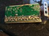
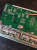
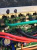
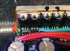
I stripped everything down and found that when the throttle is twisted and the motor tries to turn, one of the main wires to the motor would get very hot.
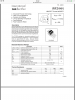
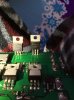
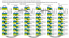
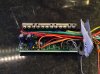
Out came the multimeter... few parts tested and then the mosfets, first 2 fine next 2 not working, next 2 fine then next 2 not working, next 2 ok then next 2 not working, “I’ve marked the dud ones with a black spot on the picture”.
Strange but may be why the motor will try to turn but doesn’t have the umf to do it.
Obviously I’m going to replace them but I’m also thinking of upgrading all of the mosfets to prevent future problems but my question is this. If I upgrade them to a higher voltage will it A. Do any damage? B. Make the scooter quicker? C. Give me further problems?
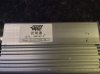
I’ve tried to include pictures of both the controller and the mosfets to give a better idea.
Can anyone recommend the correct mosfets to change them with?
Hopefully it only needs these replaced and not the whole controller £70!! Or I might just by a 2000w and upgrade everything.
Thanks for any help
E5CB09F0-B9FB-497E-BF1E-545D9648AF3F.jpeg C00D6B0D-8F1B-4F94-B0F8-DA8C68DB935D.jpeg 794E4955-0E58-4C1D-9CC8-7757D78339AB.jpeg
 
D

Deleted member 4366

Guest
Chanhging the mosfets won't give any change in speed nor power.

If you're going to get a different type of mosfet, it's best to change them all. IRFB3077 is a popular choice for a controller like that. They'll most likely make it run a bit cooler.

How many volts is it and how many amps?
Does it have an LCD?
It might be more cost effective and you get a better control system to replace the controller with a KT one.
 

gmal2017

Pedelecer
Aug 20, 2017
29
0
46
Tyne and Wear
It’s running 48v 4 x 12v 12a batteries.
They don’t have lcd displays just a basic red, orange, green battery power light near the throttle.
I was thinking of taking it up to 60v or 2000w of power but for the difference in speed to cost etc it’s probably not worth it.
 

gmal2017

Pedelecer
Aug 20, 2017
29
0
46
Tyne and Wear
Just looking at the prices of the fets you suggested, the cheapest place I can find ‘RS Components’ they’re £4 each, so if I replaced all 12 I’m looking at a bill of nearly £50! I might as well buy a 2000w controller from flee bay for £60 :(
 
D

Deleted member 4366

Guest
Just looking at the prices of the fets you suggested, the cheapest place I can find ‘RS Components’ they’re £4 each, so if I replaced all 12 I’m looking at a bill of nearly £50! I might as well buy a 2000w controller from flee bay for £60 :(
That's right. Decent mosfets that don't blow are expensive.
 
D

Deleted member 4366

Guest
You need to look up the spec.sheet. They need to be able to deal with the voltage, they need to be fast switching and they need low RDSon to prevent overheating at the phase current you use.
 

Danidl

Esteemed Pedelecer
Sep 29, 2016
8,608
12,253
73
Ireland
The nce component is by orders of magnitude more suitable... While they might both use the same TO220 package, that is where the similarities end.
 

gmal2017

Pedelecer
Aug 20, 2017
29
0
46
Tyne and Wear
Hmmm, so they might work but aren’t necessarily suitable for this application?

I’ve also a full set of the mosfets in the picture below, they came out of a 24v 110amp controller but I can’t find the specs on them anywhere.

5753EAA0-77B6-4617-9560-F4C0032CE792.jpeg
 

gmal2017

Pedelecer
Aug 20, 2017
29
0
46
Tyne and Wear
Update.....
So I’ve put new batteries in my multimeter as it wasn’t giving correct results for mosfets I knew to be working. Re-tested the old ones and they’re all fine :mad: not sure if it was down to the meter or not but miraculously they are working.
So, were to look now? The motor still judders as though it wants to turn but can’t , it freely turns by hand and up until the other day never had a problem.
 

Danidl

Esteemed Pedelecer
Sep 29, 2016
8,608
12,253
73
Ireland
Hmmm, so they might work but aren’t necessarily suitable for this application?

I’ve also a full set of the mosfets in the picture below, they came out of a 24v 110amp controller but I can’t find the specs on them anywhere.

View attachment 23442
No that was not what I said... The IR component is not in the same league as the NCE component. Were you to rip open the plastic packaging.. say crushing it in a vize , the chip for the nce component would probably be 4 times larger in area.
What's happening with the juddering is that current is going to the coils via the MOSFETs, but either one set of MOSFETs is not getting instructions to switch off and on, so the sequence is disturbed... Whether it is a controller or mosfet problem I don't know....
 

Nealh

Esteemed Pedelecer
Aug 7, 2014
20,112
8,219
60
West Sx RH
Sounds like the phase wire sequence order is incorrect or a faulty motor to controller phase wire connection. Check all connections and ensure no one wire is shorting out.

If it is phase wire sequence then use the chart below. if yours is unsensored there are 6 combos for the phase.
Don't apply full throttle if the motor isn't running properly other wise you may cause untold damage.

Phase-Hall-Wire-Combinations.png
 
Last edited:

gmal2017

Pedelecer
Aug 20, 2017
29
0
46
Tyne and Wear
Could the phase wire sequence go wrong? Everything was working ok before this happened and I hadn’t had anything out or changed any settings etc. The only thing I was doing was transferring the battery from this to my daughters buggy and back again.
The controller has never been moved, it is in a sealed off area to the rest of the scooter.
I’ve checked for loose connections but I can’t see any.
Out of the 3 main power wires to the motor the middle wire ‘green’ seems to draw a higher current as it gets very hot.
Looking at the back of the controller the soldering is a cheap looking messy job.

DD2277D4-F87F-4F46-9A38-C913BCABF71D.jpeg
 

gmal2017

Pedelecer
Aug 20, 2017
29
0
46
Tyne and Wear
Just noticed this on the back of the controller, this is the soldered joint where the negative lead comes in from the battery. Would this be an issue?

3DFC97F2-3731-40EE-9FF6-D9F648FDA2EB.jpeg


2CCD7DB3-C429-4222-BB4A-D9E405AD0961.jpeg
 
D

Deleted member 4366

Guest
I can't see it being anything to do with the wire sequence if it was working before. It's either a dodgy mosfet or a fault in the wiring between the controller and motor. There's also a small chance that it's a dodgy hall sensor in the motor.
I'd start with checking the motor wires and connectors. Did you drop it and damage the motor wire? If the phase wires use bullet connectors, make sure that the barrels are gripping them tight enough.

how did you measure the mosfets? Did you measure their resistance, which gives the best indication of problems?
 

gmal2017

Pedelecer
Aug 20, 2017
29
0
46
Tyne and Wear
The 6 mosfets I’ve marked in black do seem to be faulty, I tested them incorrectly last time using my negative lead on the gate / drain and positive on the source when, as I did in the first place, it should have been the other way round.
There is no power from Gate to the Source whereas on the other 6 there is.
So.. any chance anyone has info on these conductors as a replacement? I can’t find any info but they did come out of a 110amp controller.

DFC23F02-C1AB-4F78-B459-85677CEA7B61.jpeg
 
D

Deleted member 4366

Guest
Measure resistance between each phase wire and the battery negative, then from each phase wire to the positive. All readings should be in the range 7k to 14k and each group of three should be the same. With one group of three, you'll get interference from the capacitor/s, which will make the readings continuously change, but you're looking to compare rather than get absolute values.