Cyclamatic: The Beastamatic is dead! Long live the Beastamatic

  • Thread starter Deleted member 4366
  • Start date

Old_Dave

Esteemed Pedelecer
Sep 15, 2012
1,211
2
Dumfries & Galloway
Just to add that the cheap and easy cruise control as suggested by d8veh can be modified to also set a max speed depending on the switch position.... could also do it so the max speed is via a key switch

Sent from my iPhone using Tapatalk
 
Last edited:

evendine

Pedelecer
Jan 8, 2012
126
-1
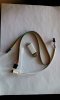
Melted wires, just means that a lot of current went through them. If you get problems with the hall wires, or if you try and hold the motor on the brakes (without cut-offs), the controller can push massive current down the phase wires - probably what caused its demise.

Makes sense - someone trying to do doughnuts on it, maybe? :p

just remember that there's thousands of Cyclamatics running around, some with modified shunts etc. and they didn't upgrade their phase wires, and neither did I when I ran with 18amp and 36v.

Yep, my 36v rig works fine with the existing wires, but can't help thinking that some of the available current must be being used to melt the insulation on the wires...

One other thing. Check that that controller doesn't have PAS precedence, i.e. you can use the throttle independently without pedalling. Jerry bought one similar and found that the PAS enabled the throttle, so no pedalling = no throttle.

Understood - thanks.
I'm struggling to make my mind up about the parameter set to send the manufacturers if I decide to go that route. Advantages are that the unit should fit without problems, is basically the standard one with some upgrades and could be programmed for different power limits / batt protection voltages and top speed. On the other hand, the BMS unit is known to work, so is a safe bet, but has size issues...

Think it would be good to try to put a recipe together for the unit that fits, but I'm not confident that i know enough to make a good job of filling the requirements sheet out. 24v or 36v, current limits, etc...
 
Last edited:

evendine

Pedelecer
Jan 8, 2012
126
-1
Wiring loom - offical manual...

Some interesting info from LSDZS (the original manufacturer of the Cyclamatic motor controller). It seems that the odd 'white wire' coming out of the controller and going straight back in is in fact the a speed limit selector signal. If the connection is made, speed limit is active, if the wire is open circuit - no speed limit is applied :)

They also sent me the wiring loom table for the Cyclamatic's standard controller (see attached).

Looks like it may be possible to get a 36v controller based on the standard one, but with a higher current limit. From what d8veh has said previously about safe current draw, 18A seems about right - comments appreciated!
 

Attachments

evendine

Pedelecer
Jan 8, 2012
126
-1
Programmer for LSWx controllers...

Some more interesting news from LSDZ - it seems you can program their LSWx controllers using the device pictured below :D

At the moment, you have to send them a list of the parameters you want changed and they'll send a file back which you can use to update the controller via a PC. I'm going to see if they'll let me have a copy of software they're using to create the configuration map, but I'm guessing it's in Chinese, so might not be much use unless translated.

Intriguing prospect of being able to build a custom configuration map library!
 

Attachments

evendine

Pedelecer
Jan 8, 2012
126
-1
Direct from LSDZS (the original manufacturer of the Cyclamatic motor controller). Started chatting about their LSW70 controller with one of their more 'switched on' tech sales staff, who has good English.

Great to know it will be possible to change the settings of a controller after purchase - lowers the risk considerably and opens up a whole set of modding possibilities :)

btw: the controller programmer rig costs $50, which seems reasonable...
 
Last edited:

NRG

Esteemed Pedelecer
Oct 6, 2009
2,592
10
$50 is a bit steep, the Xiecheng controller programming cable is about £20 but it's good there's another programmable controller out there...
 

evendine

Pedelecer
Jan 8, 2012
126
-1
Yep :), particularly one that will drop straight into the Cyclamatic wiring loom and fit into the limited space available in the standard set-up...
 
D

Deleted member 4366

Guest
I just re-read some of your previous posts. The wiring list above is not the same as a Cyclamatic unfortunately. I don't know all the differences, but it shows three-wire brake sensor connectors for the hidden wire type.

Also , that programming interface looks like a standard serial to USB interface that you can get very cheaply on ebay. I bet it'll work if you can get hold of the software.
USB 2.0 to UART TTL 6PIN Module Serial Converter CP2102 | eBay

Edit: In case it doesn't show the picture, try these:
USB 2.0 to UART TTL 6PIN Module Serial Converter CP2102 | eBay
 
Last edited by a moderator:

evendine

Pedelecer
Jan 8, 2012
126
-1
I just re-read some of your previous posts. The wiring list above is not the same as a Cyclamatic unfortunately. I don't know all the differences, but it shows three-wire brake sensor connectors for the hidden wire type.

Hmm - I take your word for it d8veh - the list was provided by the manufacturer after I gave them the serial number of the PCB, so not sure what went on there. The serial # was from a bike whose controller isn't working. Swapping to another controller makes the bike work (as described previously). Do you think the bike might have a different controller than standard and this might explain why it doesn't run properly? I've noticed that one of the brake sensor wires doesn't work - related perhaps?

Also , that programming interface looks like a standard serial to USB interface that you can get very cheaply on ebay. I bet it'll work if you can get hold of the software.
USB 2.0 to UART TTL 6PIN Module Serial Converter CP2102 | eBay

Edit: In case it doesn't show the picture, try these:
USB 2.0 to UART TTL 6PIN Module Serial Converter CP2102 | eBay

Makes sense - most MCU chips use a serial interface - just wondering whether the on-board one is rs232 or I2C. Will look into it...
..............
 
D

Deleted member 4366

Guest
The brake sensor can't work with the way that controller's wired because the connector shown has three wires instead of two. It could be adapted. The controllers might be internally the samr, but they could have different parameters in the software.
 

evendine

Pedelecer
Jan 8, 2012
126
-1
Although Cypress MCU's support In System Serial Programming (ISSP - see: In - System Serial Programming (ISSP) CY3207ISSP Software v1.999 - Cypress Semiconductor) it looks as though the USB interface provided by the controller manufacturer is I2C based and only allows you to tune parameters in the MCU (see: CY3240 - I2USB - Cypress Semiconductor), rather than completely reprogram it. To completely reprogram, you need an external hardware programmer, it seems.

The Cypress USB-I2C kit looks to be good value as it provides the software as well as the adaptor for $44, but it would be quite and undertaking to figure out which parameter is which without the help of the controller vendor, I should think...
 
D

Deleted member 4366

Guest
Good find. There's a couple of other bikes that need those small controllers as well. It looks nice and universal.

I've figured out how those three-wire brake sensors work now. When you apply the brakes, the signal wire is pulled down to ground. Two wire ones have a switch which pulls the the signal wire to ground, so the two systems are completely inter-changeable, although, if you have a two wire controller, you have to add a wire to get the 5v supply to power the three-wire sensor. If you have a three-wire controller and normal levers with switches, you just leave the red wire disconnected.
 

evendine

Pedelecer
Jan 8, 2012
126
-1
I've ordered one for my current Rat - hopefully it'll do the job :)
Gave up on the Chinese OEM's in the end - too difficult to communicate with them...
 

evendine

Pedelecer
Jan 8, 2012
126
-1
Everything seems to be working fine other than pedal assist. The sensor is wired up as follows:

Sensor Red (+5v) = controller Red (+5v)
Sensor Black (0v) = controller Black (0v)
Sensor Green (signal) = controller Blue (signal)

Magnet strip / sensor look to be properly positioned - not sure what could be causing the problem...
 
D

Deleted member 4366

Guest
The Cyclamatic sensor works backwards compared with others. Try pedalling backwards. If it works, flip the magnet disc.
 

evendine

Pedelecer
Jan 8, 2012
126
-1
Excellent advice as always d8veh! :cool: That was the problem - everything's working fine now :)

A note for anyone buying one of these controllers - it really is a tight fit. After some experimentation, i found the best way to get everything into the controller compartment was to loosen the main power connector, remove both covers, push the wires in first and then gently ease the controller in until flush with the edge of the compartment. I then packed the wires on the other side, making sure there was room for the main power connector, fitted the bottom battery plate bolts and finally screwed both covers into place...