
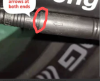
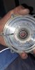
You have to push it in until the outer one reaches a ring that runs around the inner to mark how far it has to go. If you don't know about that, it's probably not in far enough.Dont understand what you want to hear. I disconnect connector from motor in order to do measurements and put back arrow against them.
Inlet into motor is according me as it should be..no visible damage
Ebike died after 200km - battery or motor failure?
- Thread starter szolo
- Start date
Ok you talk about 9pin connector, yes it is pushed to the limit. But problems occured from full drive with interruptions, then 4s drive and now only 1/4 of turn...Probably nobody play sith comnectors or display settings
Attachments
-
 602.1 KB Views: 8
Does it reach the line?Ok you talk about 9pin connector, yes it is pushed to the limit. But problems occured from full drive with interruptions, then 4s drive and now only 1/4 of turn...Probably nobody play sith comnectors or display settings
yes it is strongly connected male and female .. dont think so that here is problem, .. controller doesnt have self learn wire..
but you consider resistance between plus and phase wires that is ok? because on the internet it should be infinity, or some tens of megaOhms... but if I measure it it starts from 8kOhm and increases every seconds until forever I assume.. si this value shound be increasing during time and not starts frok KILO Ohm but at least from MEGA isnt it?
but you consider resistance between plus and phase wires that is ok? because on the internet it should be infinity, or some tens of megaOhms... but if I measure it it starts from 8kOhm and increases every seconds until forever I assume.. si this value shound be increasing during time and not starts frok KILO Ohm but at least from MEGA isnt it?
Last edited:
One last time before I give up: Does the outer reach the line?yes it is strongly connected male and female .. dont think so that here is problem, .. controller doesnt have self learn wire..
but you consider resistance between plus and phase wires that is ok? because on the internet it should be infinity, or some tens of megaOhms... but if I measure it it starts from 8kOhm and increases every seconds until forever I assume.. si this value shound be increasing during time and not starts frok KILO Ohm but at least from MEGA isnt it?

ok thanks but it is according picture... so now we need to solve if this issue is controller
- burned mosfets?, because I have same increasing impedance between Phase and + , starting from 7kOhm to xyz kOhm
?
- wrong Hall sensor - after startup of rotation controller dont get proper signals and turn of motor?
...?
- burned mosfets?, because I have same increasing impedance between Phase and + , starting from 7kOhm to xyz kOhm
- wrong Hall sensor - after startup of rotation controller dont get proper signals and turn of motor?
...?
is red led signalizing something wrong?

 youtube.com
bldc ebike shutdown
youtube.com
Attachments
-
 128.6 KB Views: 15
Good hint for another users:
You can distinguish between drive fault and accelerator leverage if you put bike into Parking mode (it runs 6kmh independently according accelerator)... for me same problem as my interaction with accelerator
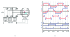
I did measurement onto wheel - hall sensor, every of three wires alternates 0V and 4.3V, when wheel is spinning.
At same time I have high level (4.3V) simultaneously on 1 a 3 wire, on 2 and 3 wire so according graph it is ok
Can I consider hall sensor as OK?
When I join two phase wire together, wheel doesnt spinning roughly (as electricity generator)...should it spin hardly isnt it?
You can distinguish between drive fault and accelerator leverage if you put bike into Parking mode (it runs 6kmh independently according accelerator)... for me same problem as my interaction with accelerator
I did measurement onto wheel - hall sensor, every of three wires alternates 0V and 4.3V, when wheel is spinning.
At same time I have high level (4.3V) simultaneously on 1 a 3 wire, on 2 and 3 wire so according graph it is ok
Can I consider hall sensor as OK?
When I join two phase wire together, wheel doesnt spinning roughly (as electricity generator)...should it spin hardly isnt it?
Attachments
-
 51.6 KB Views: 1
You can check the motor by setting your meter to measure volts (normally 20v scale), then connecting your ptobes to each pair of motor phase wires (blue +green, Yellow +blue, Blue +yellow) and spinth ewheel BACKWARDS with your hand. You should see a few volts generated . The faster you turn the wheel, the more volts you get.Good hint for another users:
You can distinguish between drive fault and accelerator leverage if you put bike into Parking mode (it runs 6kmh independently according accelerator)... for me same problem as my interaction with accelerator
I did measurement onto wheel - hall sensor, every of three wires alternates 0V and 4.3V, when wheel is spinning.
At same time I have high level (4.3V) simultaneously on 1 a 3 wire, on 2 and 3 wire so according graph it is ok
Can I consider hall sensor as OK?
When I join two phase wire together, wheel doesnt spinning roughly (as electricity generator)...should it spin hardly isnt it?
There's always the possibility that you have a bad connection at the controller end of the motor cable, Do you have an additional connector there? If you have bullet connectors on the phase wires, make sure that they're fully in and tight. Pull them apart, crimp them down a bit to make them tighter, then reconnect making sure that they're fully in.
controller arrived, swapped, and it runs only in no-hall mode..
with connected hall sensors it make 1/4 of turn as previous controller (new 9pin waterproof bullet connector from controller due to another connectors on new controller). Not tested on real road due to not accurancy with mounting wheel.. it touches brake piston every turn, need to go service...
Strange is that previously I made measurement on hall sensors and it toggled between low and high level.
Now it provides still high I assume... what can anything broken from this time? With original controller it works 200km but after 200km sensors works randomly? Are (now) damaged (?) hall sensors able to destroy (new) hall's responsible part of controller ?
I also made 6 combinations among 3 hall wires and without success.
Also display is new wxgn200 instead of s866 but it behaves similary.
Last edited:
You said your connector was in accordance with the picture. the picture show a gap between the line and the edge of the connector, which is NOT OK. The line should be in the same place as the edge of the connector with no gap. If that's not the cause of your problem, you either have a damaged motor cable or a connection fault at the controller end of the motor cable.controller arrived, swapped, and it runs only in no-hall mode..
with connected hall sensors it make 1/4 of turn as previous controller (new 9pin waterproof bullet connector from controller due to another connectors on new controller). Not tested on real road due to not accurancy with mounting wheel.. it touches brake piston every turn, need to go service...
Strange is that previously I made measurement on hall sensors and it toggled between low and high level.
Now it provides still high I assume... what can anything broken from this time? With original controller it works 200km but after 200km sensors works randomly? Are (now) damaged (?) hall sensors able to destroy (new) hall's responsible part of controller ?
I also made 6 combinations among 3 hall wires and without success.
Also display is new wxgn200 instead of s866 but it behaves similary.
yep I understand your high assumption to connector/wiring/to hall sensors. Make sense also for me but....hm... No i cant push stronger male and female against, this vertical line is plastic stopper which doesnt allow you to move it further...
Attachments
-
 312.6 KB Views: 16
problem.. wheel is spinning nicely when is under load.. small human can run it with little bit suffering on 1 gear, but regular human has problem to take off from place... motor is whining... so running motor without halls is not usable under normal usage :/
i made an measurement of hall sensors again , together with resistor and on all three wires I saw implausible values .. permanent high or low level.
Diode measurement plus versus minus cca 1000.
Plus probe on +5V against all wires cca 1400 all three. Plus probe on GND against all wires cca 666.
Minus probe on +5V or GND doesnt react.
Last edited:
SOLVED... damaged wiring to hallsensors in motor caused by speed-magnet .... magnet disassembled , put some glue on cables as isolation and it works.
But PAS is not working with new controller, colors matches on connectors (black, red,blue) , LCD is programmed to combined mode (pedal+motor support) but doesnt work..
anyways thanks all
But PAS is not working with new controller, colors matches on connectors (black, red,blue) , LCD is programmed to combined mode (pedal+motor support) but doesnt work..
anyways thanks all
Attachments
-
 739.3 KB Views: 10
 -
 187.2 KB Views: 10