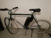
My name is Evan and I just builded a single speed ebike. Pics coming soon.
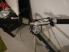
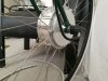
I used a 36v 250w geared front hub motor conversion kit, with a shark 36v 10ah battery.
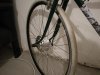
The bike is an old steel road bike, converted into single speed.
The issues that came up during installation were...
-Fork dropouts too thin for the motor axle to fit, so I had to file a little bit.
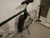
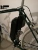
-The frame didn't have bottle cage holders to mount the battery, so I drilled 2 holes on the downtube and fitted it there.
-The kit came with pedal assist sensor, but the connector is wrong and doesn't fit with the controller, so I'll have to send it back.
-One of the brake inhibitors had the wrong connector as well, so that goes back as well.
-The thumb throttle came with an extra plastic ring, but I didn't use it. Anyone knows what's that for? Because the throttle gets stuck sometimes and doesn't spring back up.
I took the bike for a test ride and i'm very pleased, even though the battery was at 50%.
Sorry for the long post. If I m at the wrong section, please move it to the correct one.
I used a 36v 250w geared front hub motor conversion kit, with a shark 36v 10ah battery.
The bike is an old steel road bike, converted into single speed.
The issues that came up during installation were...
-Fork dropouts too thin for the motor axle to fit, so I had to file a little bit.
-The frame didn't have bottle cage holders to mount the battery, so I drilled 2 holes on the downtube and fitted it there.
-The kit came with pedal assist sensor, but the connector is wrong and doesn't fit with the controller, so I'll have to send it back.
-One of the brake inhibitors had the wrong connector as well, so that goes back as well.
-The thumb throttle came with an extra plastic ring, but I didn't use it. Anyone knows what's that for? Because the throttle gets stuck sometimes and doesn't spring back up.
I took the bike for a test ride and i'm very pleased, even though the battery was at 50%.
Sorry for the long post. If I m at the wrong section, please move it to the correct one.
Last edited: