Judders and stops when throttle pulled on

Steve Dyson

Pedelecer
Oct 13, 2018
72
13
Good afternoon, I am new here so please be gentle, Before i posted i searched for my situation and found quite a lot of advise on hall sensors for a similar issue to what i am having but i think i need to explain how i got to mine.

I built my own kit, including batteries, rode it for two weeks even in the heaviest of rain with no issues.

i must admit that the packs and contoller are just slung over the centre bar in a rucksack which means it has the chance to move about, not ideal but needed to make a housing for the whole lot.

back to the issue.

I had just been on a journey, only about 8 miles this time at 250W setting and when i went to put extra throttle on it to get up the last hill, the motor just juddered and stopped, when i pull the throttle it just jerks forward and stops.

luckily i was 5 mins from home so no big issue but it meant i had to work out the issue quick as its my daily commute to work...

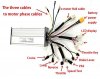
i took the batteries and controller out of the bag and found that the yellow phase wire was very hot, that hot it burnt the tip of my finger... this is obviously due to me not tightening the nut up fully and it arcing...

this in turn had melted through the black cable on the Bike light connector.

Now i am not sure if this has blown something in the controller so tested all the Mosfets and they seem to be giving almost equal results. not exact so i may change those.

I tested the Hall sensors and found that i have on the green sensor a constant 2.25V

my next step is to order some hall sensors and mosfets but the question is, do i have to match the sensors to the ones already in and if its gone so quick should i get better quality ones.

is there a standard hall sensor? or do they match the controller?

the kit i sued was the VoilaMart 250W/1500W 48V one sold on ebay... obviously its one of the cheap chinese controllers and the next question is so that i am legal on the road can i buy one of the cheap 250W controllers from ebay and attach that to the motor once i have replaced the hall sensor of course


Cheers for any advice that you can give me.
 

mikew8760

Pedelecer
Jan 9, 2018
28
1
78
Bristol
For what it's worth, I too have put together a variety of parts for my homebrew e-bike from eBay and have some experience of the electronics involved. As you suspect, it is unlikely that the MOSFET's have failed. But the result you've obtained from the 'green' Hall sensor strongly suggests it has failed. Is the 2.25 volts a constant value measured with the controller connected and powered, i.e. doesn't change as the motor is rotated? Changing a Hall sensor can be akin to brain surgery, as they tend to be firmly fixed close to the windings; practically any 'digital' type sensor should work, (not the ratiometric type). And that's after the motor has been successfully dismantled....
Good luck with your repairs.
 

Steve Dyson

Pedelecer
Oct 13, 2018
72
13
For what it's worth, I too have put together a variety of parts for my homebrew e-bike from eBay and have some experience of the electronics involved. As you suspect, it is unlikely that the MOSFET's have failed. But the result you've obtained from the 'green' Hall sensor strongly suggests it has failed. Is the 2.25 volts a constant value measured with the controller connected and powered, i.e. doesn't change as the motor is rotated? Changing a Hall sensor can be akin to brain surgery, as they tend to be firmly fixed close to the windings; practically any 'digital' type sensor should work, (not the ratiometric type). And that's after the motor has been successfully dismantled....
Good luck with your repairs.

thank you for the advice, yes its a constant 2.25v its doesnt change like the other sensors do, they flick between 0v - 4.83v

i have seen the videos on youtube replacing the hall sensor and having already had the motor in bits to check the phases, i couldnt get to the the side that the sensors were connected, so need a bit more brute force to hammer the axel out from the other side...

i will post my result once completed...

glad i am not the only one with a homebrew ebike... would be interested to see what yours turned out like
 

mikew8760

Pedelecer
Jan 9, 2018
28
1
78
Bristol
Pondering your problem with the bike, if it were me I would want to make 100% sure it was a faulty Hall sensor before attacking the hub motor. It's just possible that the input circuitry in the controller for the sensor has been fried. The simplest way to establish which is the culprit is to swap over the green Hall sensor line with either the blue or the yellow. If you still get the 2.25 volts on the green it's the Hall, if it moves to the other line it's the controller.
You also mention biking in the rain; again it's possible the controller has suffered some water ingress - many are not really 'waterproof'. My friend had a controller failure when his wife cleaned her bike with a pressure washer!! Duh!
Best of luck with your investigations and repairs.
 

Steve Dyson

Pedelecer
Oct 13, 2018
72
13
Pondering your problem with the bike, if it were me I would want to make 100% sure it was a faulty Hall sensor before attacking the hub motor. It's just possible that the input circuitry in the controller for the sensor has been fried. The simplest way to establish which is the culprit is to swap over the green Hall sensor line with either the blue or the yellow. If you still get the 2.25 volts on the green it's the Hall, if it moves to the other line it's the controller.
You also mention biking in the rain; again it's possible the controller has suffered some water ingress - many are not really 'waterproof'. My friend had a controller failure when his wife cleaned her bike with a pressure washer!! Duh!
Best of luck with your investigations and repairs.


hi mike thank you for the input, i was considering your exact theory and wondered if i powered up the controller and test only the output, if i see zero on the other 2 lines and 2.25v on the green line then it is defo the controller but not sure if it works that way..

i am pretty good with electronics and should be able to repair the circuit if i can find the piece thats the problem...
 

Steve Dyson

Pedelecer
Oct 13, 2018
72
13
Quick update on the diagnostics for this one, i swapped the blue and green hall sensor wires around from the controller and still get the same 2.25V on the blue now instead of the green.

So to summarise

First test with mult meter

Red/Black 4.85v
Black/Yellow/Yellow 0-4.79v when wheel rotated
Black/Blue/blue 0-4.79v when wheel rotated
Black/green/green 2.25v constant when wheel rotated

Second test
Red/Black 4.85v
Black/Yellow/Yellow 0-4.79v when wheel rotated
Black/Blue/green 0-4.79v when wheel rotated
Black/green/blue 2.25v constant when wheel rotated

so i am ordering some hall sensors and going to replace all 3 with some from RS componants.. and once installed will then respond with the results
 

Nealh

Esteemed Pedelecer
Aug 7, 2014
20,124
8,224
60
West Sx RH
Yellow & Blue hall ok, Green had it.
 

Steve Dyson

Pedelecer
Oct 13, 2018
72
13
Yellow & Blue hall ok, Green had it.

cheers neal, i was hoping i was on the right lines with my thoughts, its always good to try and work it out first and then if you dont understand the results, then ask the question.
 

Nealh

Esteemed Pedelecer
Aug 7, 2014
20,124
8,224
60
West Sx RH
Just another thought Steve you would get 2.25v reading if you rotated the wheel too quickly as this is just the average reading of a hall. So might be worth checking again at a very slow speed.
 

Steve Dyson

Pedelecer
Oct 13, 2018
72
13
Cheers Neal, i did that slowly as you say and it was still showing as that, i also changed the controller setting from its 250W mode to its 1500W mode and had the same issue..

cant get time to replace the sensor today but if its still an issue after i have replaced it then i have to look at the controller or the most disastrous issue of a blown phase

as a side note, i see that on mine, if i rotate it quickly the the voltage does change very quickly on my meter and shows sporadic readings, i am guessing this is because my meter isnt fast enough to keep up with the changes.
 

Nealh

Esteemed Pedelecer
Aug 7, 2014
20,124
8,224
60
West Sx RH
Phases are affected by fets going this means no power to spin the wheel.
 

Steve Dyson

Pedelecer
Oct 13, 2018
72
13
Phases are affected by fets going this means no power to spin the wheel.

the fets seem to be fine, i have tested them in diode mode and get very similar results across the board but if the hall sensor doesnt fix it then i will have to pull all the fets and test individually
 

Steve Dyson

Pedelecer
Oct 13, 2018
72
13
just a quick, i replaced all 3 hall sensors and they change values now going through the sequence, that seems correct but when i pull the throttle it still just judders so the next step for me is to look at the throttle hall sensor and see if that is goosed too, then if thats ok i will have to look at the controller... i will be ordering a cheap 48v 250W replacement and diagnosing the what may have blown on the original controller so i can understand how they are made and what happens at each stage.

i am already considering making one from an arduino and writing the code myself from some snippets of code i have found on youtube and github.


the halls were very easy to replace on mine, although i didnt like how precarious the board that they were soldered to was sat on the motor so i rewired it to a different spot and secured it better.
 

Nealh

Esteemed Pedelecer
Aug 7, 2014
20,124
8,224
60
West Sx RH
How varying were the mosfet results ? Generally all between 9 - 10 ohm reading indicates all should be well, if one is diversely worse then the other two then needs replacing.
Throttles can cause issues from moisture ingress.
Juddering is often a phase fault usually wrong wire sequence which their are 36 computations if halls are involved though could be mosfet issue if one is failing.

Phase-Hall-Wire-Combinations.png
What happens if you try to move the wheel in reverse by hand if it doesn't turn then a phase short is an issue.
 

Steve Dyson

Pedelecer
Oct 13, 2018
72
13
Turning the wheel spins freely enough, if i short a phase then it is difficult to turn and then release the short, it turns freely again...

just found the motor wire had a large wear mark (this wasnt there before testing again yesterday) as if it had snagged on something, cut the wire around it to see what was inside and any damage, could see that the blue hall wire was broken and the pase wires were stripped but not shorting.

after cutting these out, soldered all back together and i am getting 4.89v on all wire combinations to the hall sensors, this is without the phase wires connected so may be a measurement error on my part

Disconnected from the sensors and tested with colntroller and tested the contoller end hall sensor connection, this gave same results with 4.89v on all combinations... which i thought the voltage should come from the hall side not the controller side except for the 5V rail to feed power to the halls...


Its looking more and more like the controller is goosed... which i would like to work out what part is goosed but that will take time to diagnose that i dont have so will order a new controller in the mean time and get to testing the mosfets

Thank you so much for all your help so far, i am on a very steep learning curve with BLDC motors and controllers, although i have lots of electronic repair experience this is something i havent done
 

Steve Dyson

Pedelecer
Oct 13, 2018
72
13
Quick update from the replacement sensors..

i ordered some of these
https://www.ebay.co.uk/itm/281804272538

i have tested one with the motor out of the wheel and put 5v power to one, connected it to the multimeter with black lead to ground of the sensor and red lead to output of the sensor.

i put the sensor close to the magnet ring, and can see the voltage change but it only changes from 0- 0.93v as i move it round the magnets... surely this should be changing from 0-5v..

is this a dodgy batch of sensors or have i got the wrong ones...
 

mikew8760

Pedelecer
Jan 9, 2018
28
1
78
Bristol
What sensors did you get? What's the RS part number? You may have got ones that are called 'ratiometric'; these give an output voltage proportional to the magnetic field strength. (These are used in throttle controls.) The ones for phase control must be 'digital' or similar description. If so, then most are of a type called 'open collector'. This means that a pull-up resistor to Vcc (+5 volt nominal) from the sensor 'output' is needed, and the ON/OFF signal then taken from the sensor output. This pull-up resistor, anything from 10k to 47k, will be in the controller, and part of the input filter which removes (most) of the EMI (interference) picked up from the high frequency currents delivered to the stator windings.
Simplest way to check the sensors in situ, i.e. in the motor, is to add this resistor and connect your meter (or, better, a 'scope) to the sensor output. If the sensor is OK then you should see the 0 - 5 V change as the motor is slowly rotated. If you are getting this small signal with the sensors connected to the controller then something is amiss. For example, one other potential snag is that these sensors are sensitive to the polarity of the magnetic field applied. The plastic sensor package usually has chamfered edges to indicate correct orientation, but the data sheet will give details of magnetic polarity needed.
Hope this helps.
 
  • Informative
Reactions: danielrlee

Steve Dyson

Pedelecer
Oct 13, 2018
72
13
What sensors did you get? What's the RS part number? You may have got ones that are called 'ratiometric'; these give an output voltage proportional to the magnetic field strength. (These are used in throttle controls.) The ones for phase control must be 'digital' or similar description. If so, then most are of a type called 'open collector'. This means that a pull-up resistor to Vcc (+5 volt nominal) from the sensor 'output' is needed, and the ON/OFF signal then taken from the sensor output. This pull-up resistor, anything from 10k to 47k, will be in the controller, and part of the input filter which removes (most) of the EMI (interference) picked up from the high frequency currents delivered to the stator windings.
Simplest way to check the sensors in situ, i.e. in the motor, is to add this resistor and connect your meter (or, better, a 'scope) to the sensor output. If the sensor is OK then you should see the 0 - 5 V change as the motor is slowly rotated. If you are getting this small signal with the sensors connected to the controller then something is amiss. For example, one other potential snag is that these sensors are sensitive to the polarity of the magnetic field applied. The plastic sensor package usually has chamfered edges to indicate correct orientation, but the data sheet will give details of magnetic polarity needed.
Hope this helps.


Thank you mike, i was just saying about the pull up resistor and it possibly being in the controller, the ones i have are definatly bipolar digital ones... SS41F or compatible ones....

i am out to the shed to get my box of resistors out and see if i have any 10k ones to test

i bought six as i knew i may need extra in case anything went wrong

cheers for the advice...
 

Steve Dyson

Pedelecer
Oct 13, 2018
72
13
Quick update on this... finally got a replacement controller from amazon but am stumped with the Key Lock... My throttle has a Push button On off for my LCD and twist throttle.... I am ok with the Throttle side of it as they are just 5v gnd and sensor wire.... mine has a green and blue wire for the LCD which displays the battery level indicator and comes in on a green wire with 52v and has a blue wire that is connected to the GND wire, the bush button switch comes in on a purple wire at 52V and goes back down to the plug with a yellow wire.

As i said throttle i am fine with so the question is

this Key lock... how is it best connected bceause i do not want to short out another controller lol
 

Attachments

Steve Dyson

Pedelecer
Oct 13, 2018
72
13
Hall sensors in the Hub motor are now reading good as i turn the wheel... now to fix my destroyed throttle.... new linear sensor as i ripped the wires off being ham fisted.... and then hopefully out for a test ride this afternoon