Magura hydraulic brake cut-off switch

103Alex1

Esteemed Pedelecer
Sep 29, 2012
2,228
67
Going to put this on its own thread ....

Switch arrived from Germany today :). Now I just need to work out how to get it to work with my KU123 Controller !

A few basics for recap ... it's an in-line switch and I'm using it because my bike has XT combination brake/gear shift levers which I don't think will work well with a simple magnet-type solution. It's designed for BionX systems but I am told is compatible with others with some modifications, which I guess will be about the usual thing - where to connect and how to find compatible connectors !

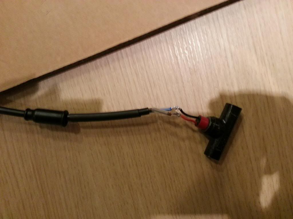
Here's an exploded photo of the switch :

20130207_130321[1].jpg

The bits at the extreme ends are just rubber gland covers. Basically, the little gold pins insert into the brake line and introduce an increase in length of 4mm on each side. The line then slides through the threaded gland, then the small round-shaped piece is slipped on, and the gland screws in to the T-piece. There is a further 2mm to allow for the small piece in the middle of the T-piece between either end so the total increase in line length is 10mm.

There is a 2-wire connection to the switch and the wires are well sealed over with a sealing compound, and covered by a rubber boot which slides on tight.

So far so good - it's a well-made unit and cost about £30.

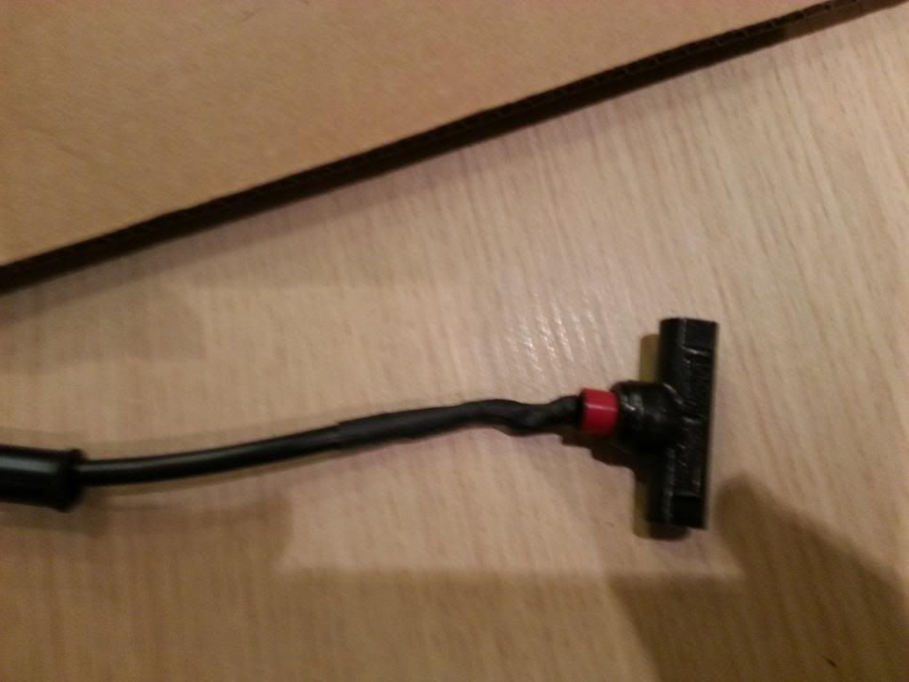
The other end has a connector like this, which appears to be a waterproof male connector sealed in :

20130207_130512[1].jpg

I guess on a BionX setup there would be a waterproof female attached to a cable which led to the controller. However this is not supplied and leaves me with the same old story I'm getting familiar with and envisaged happening - how to find a suitable coupling to take the connection to my controller... and where on the controller this fits into.

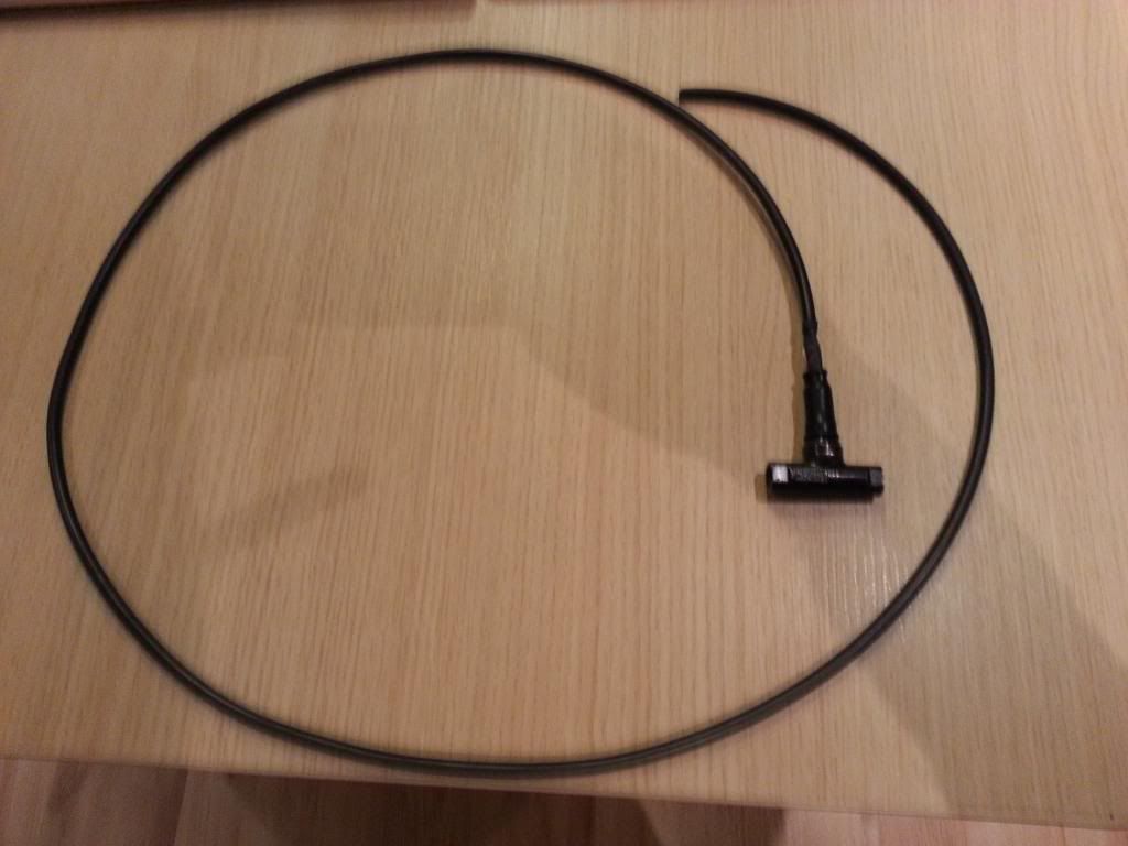
Does anyone know if you can buy leads with compatible female connectors already built in ? The length of cable attached to the switch is very short :)rolleyes:) so I am guessing the connector is likely to be external as a result and so a longer length coupling lead is likely to be most flexible for various controller locations.
 
Last edited:

Old_Dave

Esteemed Pedelecer
Sep 15, 2012
1,211
2
Dumfries & Galloway
To save messing around with connectors, I'd advise cutting off the red and black wires from the switch and solder longer ones on (the connections will be covered by the rubber sleeve.)

But first..... Fit the switch :p


Sent from my iPhone using Tapatalk
 

103Alex1

Esteemed Pedelecer
Sep 29, 2012
2,228
67
Controller end

The KU123 controller has a 2-wire input connection labelled low voltage brake wire (seen here on the right with blue/yellow) and seems tied in to a mystery black connector in the middle (3-wrie / small black connector - of which the red wire is tied in to the throttle array and splits off it).

20130207_131424[1].jpg

I am guessing that the 2 wire input connection labelled low voltage brake wire is what will connect to the switch but would be good to get some help with this as that is only a wild guess based on there being 2 wires.

The controller also has a single wire labelled high voltage brake wire with its own connector which I have no idea what it is for :

20130207_131445[1].jpg
 

103Alex1

Esteemed Pedelecer
Sep 29, 2012
2,228
67
To save messing around with connectors, I'd advise cutting off the red and black wires from the switch and solder longer ones on (the connections will be covered by the rubber sleeve.)
I can't really do that Old_Dave - there is no solder point on the outside under the sleeve (it's a proper weatherproof external fitting and everything is sealed in under wax-type sealing compound so without completely breaking open the switch there's no way to get at that end, only the connector end.

You can see from this photo more easily :

20130207_130331[1].jpg

But first..... Fit the switch :p
Nah ... if I fit the switch I can't send it back and I'm not convinced it is suitable if the connections can't be properly sorted so reluctant to fit it unless I can get a proper compatible connector to fit the controller or be sure that alternative cabling can be soldered to it and restored like it is. Also don't want to cut my brake cable unless this switch is definitely going to be used as otherwise I will need to buy another hydraulic brake line if it isn't.

I can't believe this unit is sold without there being able to be compatible couplings. That would just be stupid !

The next complete rewrite on account of connector compatibility issues could still be chucking the combined shifters and replacing with standalone XT shifters and brake levers which people seem to understand how to get to work with different types of simple cutoff switches.

Reluctant to do that though because this conversion is going to run on cost wise a lot more than I had budgeted with fundamental bike setup mods of that magnitude. Set-backs at every turn with this build !
 
Last edited:

103Alex1

Esteemed Pedelecer
Sep 29, 2012
2,228
67
Just a thought ... what is that black stuff sealing over the wires going in to the switch unit ? Maybe it's possible to get some to restore to like condition if it was removed to get to the soldering points... and it would be good for sealing other connections too.

Someone must surely know where you can get lengths of cable (it's 20AWG) with moulded connectors attached like the ones on this switch. They are the same as the ones on external batteries for XML lights etc.

In fact I've got to replace one on a battery pack for CREE light where the connector came loose and caught in a wheel spoke, shearing the cable sheath right where it comes out of the connector. So I could get one to fix that too at the same time. What is this type of connector actually called - does anyone know ? I can go off searching if I know what to look for. Asked in Maplins whether you could get them and got a "dunno" in response lol.
 
Last edited:

Old_Dave

Esteemed Pedelecer
Sep 15, 2012
1,211
2
Dumfries & Galloway
Cut the wires about 1" away from where they disappear into the switch, trim back about 1/4" of the insulation so that you can extend the wires by making a soldered joint,

Now fit it


Sent from my iPhone using Tapatalk
 

103Alex1

Esteemed Pedelecer
Sep 29, 2012
2,228
67
Cut the wires about 1" away from where they disappear into the switch, trim back about 1/4" of the insulation so that you can extend the wires by making a soldered joint,

Now fit it
Oh - I SEE ... so you solder, shrinkwrap and make sure the little rubber boot slides up over the top ? (Doh !)

Still have to work out where to locate the switch ... the instructions say this ...

20130207_130538[1].jpg

What do they mean by that in 4 ? Are they just saying to make sure the cable is vertical whilst you bleed the system and not as an orientation of the 'T' when you pick a place to install it ? :confused:

Investigating cable cutters - if I buy some will get some decent ones that I can use on any future jobs but may take the bike up to a shop I can walk it back home from and ask them to cut a 10mm section out for me when I've worked out where best to put it on the bike. Probably next week now.

Still need to sort out where it connects to the controller too... and looking at it going to have to source a connector for the controller end in any event. Wish I'd known the couplings for controller connectors were so hard to get hold of I'd have asked BMS to send me a load of spares !
 
Last edited:

Old_Dave

Esteemed Pedelecer
Sep 15, 2012
1,211
2
Dumfries & Galloway
In the absence of decent suitable cutters, I'd suggest a fine tooth saw blade... Like a junior hacksaw blade and then clean any burs from the external / internal edges using a something like a craft knife. (clean the edges only)

Order of works.

Fit the switch
Bleed the brakes
Solder the extra wire on
Attach to controller

One problem at a time.... Fit the switch, lol


Sent from my iPhone using Tapatalk
 
Last edited:
D

Deleted member 4366

Guest
There's an interesting change in the controller. I just checked my latest one and it''s the same as yours. It now has a three-wire connector for the hidden wire break switches, which'll save a lot of messing about for those that want to use them.

You need the white connector with black and yellow wires. All you need is the matching connector with a piece of wire connected (with two conductors). I'd cut off the jack plug from your Magura switch near the jack plug, and then you only nee to solder the two wires, a bit of heat-shrink. Job done. Luckily I have the connector you need, so I'll put it with the other one.

In the meantime, you should install the switch, and then you can test that it works by using a multi-meter on bleep.You put one probe up the middle and the other on the outside of the connector and it should bleep when you operate the brake. Then you can do what's suggested above.
 

103Alex1

Esteemed Pedelecer
Sep 29, 2012
2,228
67
Luckily I have the connector you need, so I'll put it with the other one.
You're a life-saver ... would be a bit lost otherwise ! :)

In the meantime, you should install the switch, and then you can test that it works by using a multi-meter on bleep.You put one probe up the middle and the other on the outside of the connector and it should bleep when you operate the brake. Then you can do what's suggested above.
OK will come back to this. Off to the sorting office where hopefully my multimeter is waiting to be collected.
 

103Alex1

Esteemed Pedelecer
Sep 29, 2012
2,228
67
In the absence of decent suitable cutters, I'd suggest a fine tooth saw blade... Like a junior hacksaw blade and then clean any burs from the external / internal edges using a something like a craft knife. (clean the edges only)
Could I christen my new Dremel-type multi tool and use that instead ? I broke the hacksaw blade fixing levers on the one from the model shop inside 10 seconds of trying to set it up so don't have one now ... tool was made of butter !!!!! The £5 American precision stanley-type blade knife from same shop broke inside a day and bits of blade flew across the kitchen. I have one from Tesco now which is man enough to be in my hands ... (well - just about !)
 
Last edited:

Old_Dave

Esteemed Pedelecer
Sep 15, 2012
1,211
2
Dumfries & Galloway
Best advice ... Get a new hacksaw blade or pack of 10, the dremel may cut too fast and at an angle of your not used to it


Sent from my iPhone using Tapatalk
 

103Alex1

Esteemed Pedelecer
Sep 29, 2012
2,228
67
Best advice ... Get a new hacksaw blade or pack of 10, the dremel may cut too fast and at an angle of your not used to it
Haha ... I broke the hacksaw itself not the blade ... know what you mean about the power tool but I can use it on low, take 20 secs or so over it and can't face buying another hacksaw just yet if I can get away with it.

Hi Alex

you need one off the following

I bet you cant break it

HITACHI G23SS 240 VOLT ANGLE GRINDER 230MM 9 INCH | eBay


Frank
:D ... now that looks like exactly my kind of tool... always wanted an angle grinder. Would be up there with my chainsaws ;) Not sure the hydraulic brake line would take to it as much as I do tho' :eek:
 
D

Deleted member 4366

Guest
Did you get a toolkit for your Dremmel? If so, there should be some cutting discs in there like a mini angle grinder - perfect for the job. There's a picture of one down this page:
mini MAP - Page 5
 

103Alex1

Esteemed Pedelecer
Sep 29, 2012
2,228
67
Did you get a toolkit for your Dremmel? If so, there should be some cutting discs in there like a mini angle grinder - perfect for the job. There's a picture of one down this page:
mini MAP - Page 5
Yep ... I have the "105pc kit" with it so shd have one of these. Does it cut the line or do you saw it through and then finish off the ends with this tool ? I keep half-understanding the posts people put up on various forums about using this tool in gear / break line cuts. Some say they cut and use it to finish others don't say anything about cutting and just talk about the tool ! One is supposed to have either cut a line or used the tool/fitting before I guess and understand from that ...

Probably do this job when I get back next week as away tomorrow for a few days. In the meantime I have done as much as I can ...
 

103Alex1

Esteemed Pedelecer
Sep 29, 2012
2,228
67
Rewiring - step 1

Took the bull by the horns and re-wired the switch tonight ready to be joined to a new connector that fits my controller which D8veh is kindly sending me (couldn't find where to get one here) :


Wires tinned and hooked to new 2-core flex from Maplins which is exactly the same diameter. Wires from switch are silver 20awg and flex is copper-wired but I am hoping that's OK because 2-core 20AWG is about £10 a metre in UK :eek: (what a racket !)

Clear shrinkwrap on each core ready to cover the solder joints and black to go over both when finished. The switch boot in place on the flex ready too.

Done :


Just the boot to slide back up now (it's a bit of a job - very tight and prone to pull the shrinkwrap with it !) - but just managed it and shrunk very tight. I'm using stuff from a car parts place (because it's there to use) but it needs a LOT of heat to work (soldering iron held close helps - as per previous tip).

Here's the finished mod attached to 1m of flex so plenty of room to play with controller position. I'll fit the connector to the other end when it comes through and I've decided how long the cable length needs to be :

 
Last edited:
D

Deleted member 4366

Guest
There should be a pin (mandrel) in the kit with two small red fibre washers on the end held down by a screw. Take the screw out and remove one washer. Push the screw through the disc (its tight), put the other washer on and screw it onto the pin so that it looks like the picture in the link above.

To cut the tube, bend it into an arc so you can bring the cutter down at right-angles. Use medium/high speed. You must be careful not to apply any bending force to the disc or it'll break. Once you've cut through, you can make the ends nice and square using the face of the disc, but be gentle. Finally hook out any debris from the tube.