[QUOTE="Matthew Hutchinson, post: 440658, member: 22491]
Edit just realised that of course it would have turned it on, the whole point in shorting the red and blue is to bypass the switch[/QUOTE]
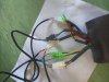
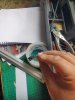
Yes, I pulled out my unused elifebike controller. It uses the 810led. Jumpered the correct two wires and saw that the throttle was able to spin the motor without the 810 connected, so that that suggests you have indeed proved your controller is likely dead,
Edit just realised that of course it would have turned it on, the whole point in shorting the red and blue is to bypass the switch[/QUOTE]
Yes, I pulled out my unused elifebike controller. It uses the 810led. Jumpered the correct two wires and saw that the throttle was able to spin the motor without the 810 connected, so that that suggests you have indeed proved your controller is likely dead,