If you have a larger pack (15 Ah or bigger), charging at 2A can take quite a long time. On some occasions this this can be far longer than desirable. So if you need to refill your pack a little quicker, what are the options for doing this in a safe way? 3A chargers are available and I have used one for some time, but I wanted something around 5A, so I can recharge in just a few hours. For a 15 Ah pack, with 6p banks this is still less than 1 A per cell and this is less than the charging rate of many USB banks.
Before charging any battery with an eBay charger or one from similar sites, it's always advisable to check it inside and out to make sure it is safe and fit for purpose. I do not recommend doing this is you do not know what you are doing. This information is provided for general interest, but it should only be acted upon by forum members with suitable expertise. Charging batteries is dangerous. Opening mains appliances is dangerous. Modifying will invalidate warranty and if you do it wrong you could burn your house down etc, etc...you get the idea.
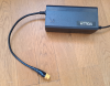
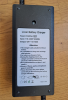
I found this one on eBay and it looked interesting:
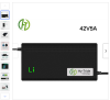
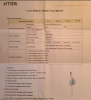
It came with some basic info:
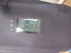
So the spec for the voltage was 42 +/- 0.3 V. When measured, the output voltage was 42.1 V and the current was 4.7 A. It weighed in at 355 g. The cable retainer on the output was quite a sloppy fit for the case and it rattled around a bit. So to the insides...
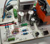
It was held together with a couple of anti tamper screws, but a suitably sized flat balded screw driver got them out. It came apart quite easily after that...
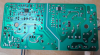
Soldering was not too bad, no dry joints and not too much spatter, although there were a few blobs that could come loose in use:

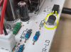
I wasn't happy with the output being over 42V and as I only charge my packs to 41V I wanted to modify the output of the unit. In this case, the 431 IC voltage reference that controls the output voltage was a TO92 rather than a surface mount:
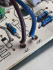
Then it was a case of finding the voltage divider chain. This had me stumped for a while, as I assumed blue would mean negative and brown positive, but I eventually read the text on the board and found this wasn't the case! There was also a big blocking diode between the output and ground. But eventually I traced it out.
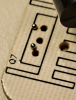
I desoldered the 11k resistor and added a 300 Ohm resistor to the chain. The voltage increased to 42.493 V. So after a bit of trial and error, I replaced the 11k resistor with a 10k and a 100 Ohm to give 41.087 V. I left it at that because I've often found that if you are using a Watt meter, the shunt inside it drops the voltage by about 50 mV.
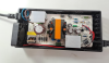
I wasn't happy with the output cable, it was too thin for my liking, considering it will be taking 5A. I found some thicker cable, with nice red and black coloured wires. I bored the holes in the PCB slightly larger to take the thicker wire. I put an XT60 connector on the end. I also had a spare cable retainer knocking about from another project that was a nice snug fit for the case and this was attached to the cable with some superglue:
Before charging any battery with an eBay charger or one from similar sites, it's always advisable to check it inside and out to make sure it is safe and fit for purpose. I do not recommend doing this is you do not know what you are doing. This information is provided for general interest, but it should only be acted upon by forum members with suitable expertise. Charging batteries is dangerous. Opening mains appliances is dangerous. Modifying will invalidate warranty and if you do it wrong you could burn your house down etc, etc...you get the idea.
I found this one on eBay and it looked interesting:
It came with some basic info:
So the spec for the voltage was 42 +/- 0.3 V. When measured, the output voltage was 42.1 V and the current was 4.7 A. It weighed in at 355 g. The cable retainer on the output was quite a sloppy fit for the case and it rattled around a bit. So to the insides...
It was held together with a couple of anti tamper screws, but a suitably sized flat balded screw driver got them out. It came apart quite easily after that...
Soldering was not too bad, no dry joints and not too much spatter, although there were a few blobs that could come loose in use:
I wasn't happy with the output being over 42V and as I only charge my packs to 41V I wanted to modify the output of the unit. In this case, the 431 IC voltage reference that controls the output voltage was a TO92 rather than a surface mount:
Then it was a case of finding the voltage divider chain. This had me stumped for a while, as I assumed blue would mean negative and brown positive, but I eventually read the text on the board and found this wasn't the case! There was also a big blocking diode between the output and ground. But eventually I traced it out.
I desoldered the 11k resistor and added a 300 Ohm resistor to the chain. The voltage increased to 42.493 V. So after a bit of trial and error, I replaced the 11k resistor with a 10k and a 100 Ohm to give 41.087 V. I left it at that because I've often found that if you are using a Watt meter, the shunt inside it drops the voltage by about 50 mV.
I wasn't happy with the output cable, it was too thin for my liking, considering it will be taking 5A. I found some thicker cable, with nice red and black coloured wires. I bored the holes in the PCB slightly larger to take the thicker wire. I put an XT60 connector on the end. I also had a spare cable retainer knocking about from another project that was a nice snug fit for the case and this was attached to the cable with some superglue:
Last edited: