

Hi all, I'm trying to get my head around having my bike set up with the least power resistance possible and cant seem to find any 'bike specific' correlating answers?
Here's a low-down of what I think I understand so far and some questions that I have...
Firstly, It's a bit silly to splash out on a mega motor, battery and controller set up, without thinking about the most efficient power flow through various connectors and cables etc. Quite a bit of power can be lost through using the wrong components for this
I'll prob end up using XT150 connectors anyhow but would like to get to the bottom of this conundrum.
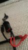
The above picture shows an Anderson connector rated for 50amps, A smaller Anderson rated for 45amps and a key switch connection rated for 10amps.
As you can see, there is a huge difference in size between the large and small Anderson which have pretty much the same rating. The 45amp Anderson and the 10amp rated keyswitch are about the same size.
I think I understand that the rating is not to do so much with the metal connection but more so to do with the cable size that each connector can take. Both these Andersons can take 10awg wire and so they are rated about the same.
10awg cable is rated for a max of 52amps, hence a connector rating of around the same figure.
I think however that this cable rating, is for use on longer runs, household electric etc and for short runs, as on an electric bike, they can actually take a lot more current.
Please correct me on this if anyone knows better?
So, down to my specific query!
I've been using a key switch, purchased from Crystalyte, which connects and disconnects the main battery supply (full voltage) to and from the rest of the bike, as below.
I though that I'd try to make up my own keyswitch and purchased a cheap £3 10amp rated ignition switch, took it apart and it has exactly the same switching internals as the Crystalyte one which is being used on high power builds all over the world.
So my very long winded question, is
Does anyone actually know how much power is lost through these small copper connectors and also how much is actually lost through small runs of cable compared to the longer runs that cable is usually rated for?
I could start taking reading but thought I may as well ask here first
")
btw, Ive been running around 80amps through this Crystalyte keyswitch with no problems, which is a bit strange considering that it is basically the same as a 10amp ignition switch.
I put on a 10amp ignition switch today, connected directly to the pack and again had no problems running it. Not sure how much, if any power was being lost through the connection though?