Bafang swxk wiring confusion

jonathan75

Esteemed Pedelecer
Apr 24, 2013
794
213
Hertfordshire
*holds head in bafflement*

Why, elifebike, why...

Actually the second is Greenbikekit and I don't see it as quite as annoying but I still don't know what to put where. Would be really grateful for any advice.


chain

Pedelecer
Jul 14, 2011
56
4
Be certain the battery is switched off. If you can unplug the wire from the battery, do so.

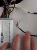
Something might be learned from a study of the plugs and sockets already attached to the wires. After all the different ones which can be plugged together have been plugged together, check them one by one and unplug those which are precisely alike (pins, size, shape, gender, locks) as possibly in error. Now see if you can match wire color. A hint can often be found in wiring coming out of the controller in several bundles; mostly those in a bundle belong to a single function. Now you should have fewer wires left, even, if you're lucky, none.

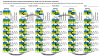
Go back to the pages from which you bought these items and search them for a link to a diagram, normally one or two pages that tells you the colours of the wires and what they link to. Also try the page for the controller, because that almost always has a very explicit diagram and text. If you cannot find these information sheets on the pages, or on the seller's download site, or by a general search of the net, ask for them.
 
D

Deleted member 4366

Guest
I'll tell you why. They've left the connector blocks off to make things easy for you.

The top photo shows your motor wires. Without knowing what else you have, what can one say other than connect them to the corresponding connectors on the controller. There should be a white block to house the five thinner hall sensor wires.
You clip the wires into the block to match the sequence on the controller, but don't do it until you've threaded the wire through where it has to go otherwise you have to take the block off again, which is tricky.

If you have the 9-pin motor connector on your controller, you'll have to cut wires and join them to get matching connectors.

Tell us what you've got so we can give specific advice.
 

trex

Esteemed Pedelecer
May 15, 2011
7,703
2,671
those blades you see are the hall wires. They fit into a 6-way AMP plug like this one:


red and black are power, yello green and blue are signals.
 

jonathan75

Esteemed Pedelecer
Apr 24, 2013
794
213
Hertfordshire
This is brilliant, thanks for your advice Trex, D8veh, and Chain, I'll do as much as I can with the information given and post again when the next issue arises. I have two controllers, a 14a and a 10a, pictures to follow. I think the next issue is going to be with the two hidden wire brake sensors, which correspond with one but not another of the brake plugs on each controller (and certainly don't correspond with the wire colours on those plugs). Pics in a second.
 
D

Deleted member 4366

Guest
Hidden wire brake sensors have unusual colours. Blue is signal, yellow ground and red 5v. You need to spread out the connectors to show what you have. I doubt that the one on the left has a connector for HWBS, so you have to add a connector by soldering a red to a spare 5v pad on the pcb or splice one into the throttle red. The other two wires go to the 2-wire connector - black to black and signal to signal.
 
Last edited by a moderator:

jonathan75

Esteemed Pedelecer
Apr 24, 2013
794
213
Hertfordshire
Hidden wire brake sensors have unusual colours. Blue is signal, yellow ground and red 5v. You need to spread out the connectors to show what you have. I doubt that the one on the left has a connector for HWBS, so you have to add a connector by soldering a red to a spare 5v pad on the pcb or splice one into the throttle red. The other two wires go to the 2-wire connector - black to black and signal to signal.
Thanks. I've pasted below a photo of an actual brake lever connected to the controller's brake connector, and then the bare wires of the HWBS splayed next to it.

upload_2015-4-28_16-24-12.jpeg
 

jonathan75

Esteemed Pedelecer
Apr 24, 2013
794
213
Hertfordshire
Oh dear. All wired up for motor test (before sorting brake issue - no brake cutoffs installed), LCD on ok, headlight on/off ok, turn throttle, no power. Check all wires, wires appear to be in the places they ought to be. Could controller be at fault? It's this one.
 

jonathan75

Esteemed Pedelecer
Apr 24, 2013
794
213
Hertfordshire
I've tried to test another controller with led rather than lcd display, however the battery connections don't match the 'pole' type battery connection on my type 09 battery. Does anybody know what would be a good next step please? I've got as far as I can without buying more stuff.
 
D

Deleted member 4366

Guest
For testing, you should leave everything disconnected that you don't need, i.e. you should connect only the motor, battery, throttle and LCD.
 
  • Like
Reactions: jonathan75

shemozzle999

Esteemed Pedelecer
Sep 28, 2009
2,826
686
Oh dear. All wired up for motor test (before sorting brake issue - no brake cutoffs installed), LCD on ok, headlight on/off ok, turn throttle, no power. Check all wires, wires appear to be in the places they ought to be. Could controller be at fault? It's this one.
Hi jonathan,

Pedelease also sell this kit they show instructions for setting up the LCD on the link below - they say you need to set parameters P09=0 and P10=1 on the LCD for the motor to run on throttle only without the PAS i.e. the magnet disc and sensor.

http://pedalease.co.uk/index.php?rt=product/product&product_id=13172304
 
  • Like
Reactions: jonathan75

jonathan75

Esteemed Pedelecer
Apr 24, 2013
794
213
Hertfordshire
While the SWXK was spinning, the CST wasn't responding, unfortunately. I wonder if that had to do with the fact that the controller connector had an extra white wire on the CST side, and on the controller side there wasn't anything. Just rechecked both again and same. The blue bullet connector came off the CST afterwards, not sure if that could have been responsible, although doubt it.

Also, the barrel connectors for the battery, are too large on the red and too small on the black. The latter I can remedy by stretching it, but the former I can't squeeze smaller. I wonder if wedging some pieces of ferrous material into the gap might hold it tight. Doesn't quite feel right somehow though.
 
Last edited:
D

Deleted member 4366

Guest
The white wire doesn't have any effect on the motor operation. It's a speed sensor for the lcd.

On the other hand, the blue bullet coming off could be the problem, but, if the connection was still OK, it could be the connection sequence. You can't always connect colour to colour. Sometimes, you have to find the correct sequence by trial and error.
 
  • Like
Reactions: jonathan75

jonathan75

Esteemed Pedelecer
Apr 24, 2013
794
213
Hertfordshire
The white wire doesn't have any effect on the motor operation. It's a speed sensor for the lcd.

On the other hand, the blue bullet coming off could be the problem, but, if the connection was still OK, it could be the connection sequence. You can't always connect colour to colour. Sometimes, you have to find the correct sequence by trial and error.
I've bought some crocodile test clips and tried a dozen or so combinations but I gather there are many many permutations possible between the five active wires. I think just laying out a graph of possible permutations will take me a few hours, let alone testing them. I don't have a mathematical method for it so it would be just a manual excel spreadsheet ad hoc.

I've emailed Steven Deng at elifebike, really not sure what to do now.
 
  • Useful
Reactions: Carrog42
D

Deleted member 4366

Guest
There's 36 combinations of the three phase wires and three hall wires. Three combinations will give correct forward operation. The red and black hall wires are fixed.
 
  • Like
Reactions: jonathan75

jonathan75

Esteemed Pedelecer
Apr 24, 2013
794
213
Hertfordshire
Thank you John and D8veh, that wiring diagram is brilliant. So I've been through every configuration on the list and unfortunately not a peep from the CST. I then tested the setup on the SWXK and it worked, suggesting the setup was sound. I'm not sure where to go from this point. Apologies for the note of helplessness.