Battery capacity drop

Khumarahn

Pedelecer
Feb 4, 2014
60
3
41
Hi All,

I assembled my bicycle in April-May

2014_08_01-bicycle.small.jpeg

I am quite happy with it, but recently I noticed that my range lowered very significantly. I made a discharge circuit and discharged the battery from full, taking note of voltage and current and computing the capacity.
battery.a.png

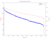
I measured 183 Wh. That is something like 5 Ah, while it is supposed to be 10.4 Ah.

I was using the bicycle every week day as commuter, I covered around 1000 miles since I installed the motor.

My question is, is this decrease in capacity normal?
 
D

Deleted member 4366

Guest
It's certainly not normal. You need to take the top and the bottom off to check if water's getting in. Do you ride in the rain?

If it's not water then there's less hope. You need to check the cell voltages on the multipin connector at the BMS.
 

Khumarahn

Pedelecer
Feb 4, 2014
60
3
41
Hi d8veh, thanks for helping me again :)

I disassembled it a couple of days ago, haven't found any water. I didn't ride in rain for a long time. I thought I might find a broken cable, or some obvious damage, but I haven't. Where are multipin connectors, and what voltages should they have?
 

amigafan2003

Esteemed Pedelecer
Jul 12, 2011
1,389
139
You're a couple of volts short of a full charge there - should be 42v. I think you've got a bad cell in the battery.

If you can take a photo of the opened battery that would help and we can tell you where to measure the voltages.
 

Khumarahn

Pedelecer
Feb 4, 2014
60
3
41
Here is a photo of the open battery. I see two multipin connectors on top. If these are the right connectors, what voltages should I expect?
2014-08-29 18.30.50.jpg
 
D

Deleted member 4366

Guest
That's an interesting one. The daughter board on top must be the DC/DC converter for the USB.

Those two white connectors with 5ive and six pins on opposite sides are the wires from the cells. They're in a strange sequence. From memory, pin one on one side is cell 1, then it swaps to pin 1 and 2 on connector 2 for cells 2 and 3, then it swaps back to connector 1 pins 2 and 3 for cells 4 and 5, then back to connector 2 and so on. All you need to do is put your black probe on the thick wire from the cells marked B-, then put your red probe on each of the 11 connection points. You don't need to unplug them because you can get your probe onto the pcb connections. Post the 11 results here, and then we can decide what to do.
 

Khumarahn

Pedelecer
Feb 4, 2014
60
3
41
Here are 11 voltages, measured between B- and 11 pins as on the picture (6 on the left, 5 on the right):
36.1
32.1 40.2
28.1 12.07
24.1 8.05
20.0 4.02
16.08 0.0

I observed a strange thing: voltage on usb port is 2.8.

P.S.: the battery is not yet fully charged after the discharge test. I removed charger when making the measurements.
 
D

Deleted member 4366

Guest
I calculate:
4.1
4.0
4.0
4.0
4.1
3.9
4.0
4.0
4.0
4.0

so nothing to worry about there. I wonder if the DC/DC converter is faulty. Is it possible to remove the pcb from the BMS?
 

Khumarahn

Pedelecer
Feb 4, 2014
60
3
41
do you mean the very top pcb from which usb cables run down? I think I could unsolder it, it shouldn't be difficult
 

Khumarahn

Pedelecer
Feb 4, 2014
60
3
41
I unsoldered the top pcb. I couldn't do it as clean as I wanted... May not be able to install it back. Not that I would try :)

IMG_2548.JPG
what now? did I gain access to something that was hidden?
 

Khumarahn

Pedelecer
Feb 4, 2014
60
3
41
I don't really understand yet, what to look for. I measured, while discharging, on this picture:
IMG_2550.JPG
measured voltages between neighboring contacts circled in red, I got
3.78 3.03 4.47 3.81 3.75 3.76 3.77 3.74 3.75
Overall voltage of the battery was something like 37.5 at the moment of measurements. This looks strange.
 
D

Deleted member 4366

Guest
If you take 0,7 from no.4 and add it to no.3, it would be normal. Can you do the measurements again, but use the B- for your black probe?

Those black resistors are the bleed resistors used for balancing the cells. Normally, transistors open them when the cells are full to give the others a chance to catch up.
 

trex

Esteemed Pedelecer
May 15, 2011
7,703
2,671
The drop in voltage became sharp after 33.5V-34V whereas in a good battery that should have been around 32V, one of your cells is damaged and not easy to spot because that cell worked well above 3.4V.
My suggestion is to increase the discharge current to 10A - the faulty cell will collapse much earlier and may even die - much easier to spot then.
 

Khumarahn

Pedelecer
Feb 4, 2014
60
3
41
Here are 10 voltages between B- and ten red circled spots as before. This time measurements are done an a fully charged battery with no load. There is the same unevenness as before, but I don't know what it means.
36.7 32.6 29.3 24.5 20.4 16.4 12.3 8.2 4.1 0.0

I can't increase the discharge current to 10A - I have no suitable discharge circuit.

When I am told that I have a bad cell, what does it mean? Is cell a group of 4 batteries, or a single one? And is there a quick way to test individual batteries/cells for goodness?
 

trex

Esteemed Pedelecer
May 15, 2011
7,703
2,671
bottle batteries are very hard to fix. I think only d8veh can fix these batteries.
I've tried and given up because I don't have the patience.
The cells are grouped by 4 as you already know, you need to locate the cluster that is weak, then ungroup and test each cell using something like an imax B6.
To find which cluster is weak, you need to monitor the clusters at around 35V then again near the LVC, in your case, around 33V, or about 70min and 90min into your discharge test. Compare the two sets of figures and spot which one has the biggest drop in voltage.
 
D

Deleted member 4366

Guest
Those results don't look right, so i guess something is wrong with the BMS. I would have expected the values to be more or less the same as those measured at the connectors. The bleed resistors only come on when the cell's fully charged, so try unplugging the two connectors and measure resistance between the connector pins (pads on pcb) and the opposite side of the bleed resistors to see if any are switched on. You could also measure the resistance of the bleed resistors where those anomalous voltages are.

I don't believe that there's anything wrong with the cells in your battery unless they're all reduced in capacity.
 

Khumarahn

Pedelecer
Feb 4, 2014
60
3
41
Very interesting. I unplugged both multipin connectors and measured the resistance between connector terminals and corresponding ends of three-legged black chips, like on the picture.
IMG_2554.JPG
Everywhere picture is roughly the same: 0.0 Ohm to the upper left, >10 MOhm to the upper right and >0.3 MOhm to the bottom. Except B7 with
(0.0 Ohm, 87KOhm, 87KOhm) and B8 (0 Ohm, 19KOhm, 56KOhm).

Also, the resistances between top right and bottom pins of ten three-legged chips show anomality: for everything but B7 and B8 they are infinite, but for 7 and 8 they are 31 KOhm and 7KOhm).

And strange voltages above happened near B7 and B8 also.
 
Last edited:
D

Deleted member 4366

Guest
Can you measure resistance between the connector pins and the bottom and of the bleed resistors. It should be open if the transistors are switched off or 100 ohms if switched on.

With the connectors in, do any of the resistors become warm or hot?
 

Khumarahn

Pedelecer
Feb 4, 2014
60
3
41
Sorry, I didn't exactly understand what you are asking. Resistance of every bleed resistor is around 98 Ohm. Resistance between top ends of bleed resistors and bottom pins of three-legged chips is 0. Resistance from connector pins to each end of bleed resistors is very high for B1-B6 and B9-B10, and for B7 it is 80 KOhm and for B8 it is 56 KOhm.

When connectors are plugged in, but battery is not charging and there is no load, voltages on all resistors are zero, except 52mV on 7th and 0.7V on 8th.

Looks strange, does it?