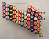
For best current share I would try a build like this. I remarked your pic so a bit crude with paint lines.
Place an extra insulator on all + ends.
Wrap each cell with Kapton tape (on top of the original shrink), hot glue together won't shrink or melt Kapton or use grip fill for a better bond.
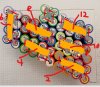
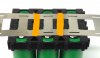
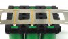
The grey is nickel welded in an X at the center and is the P connection, the yellow is the series connection using copper strip.
Solder the copper strip to the centre of the nickel X.
Make up a jig to spot weld only the X join and then solder the copper strip to a pair of Nickel X's, then spot weld the paired nickel X's to the cell ends ( this stops any solder heat to the cells).
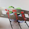
The red numbers are the even cell sense wires and can simply be soldered to the middle of each of the series buss's.
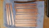
A 10mm x 0.2mm cooper strip = 2mm2 so good for 32a if you need better current share use a 15mm wide copper strip or go 10mm x 0.3mm for 48a current ability.
A wider buss will dissipate heat and current better then a narrow thicker one.
For the current path each nickel buss need to be the same size and length, all copper buss length need to be the same as each other.
View attachment 28536
The nickel X you could double up if using 10a cells, though if using a 15mm copper strip the nickel current path to the copper is very short so heat should not be an issue and the copper will transfer it very quickly.

")