
BBS01 to KT controller mod.
- Thread starter Nealh
- Start date
Firstly order your controller.

 www.aliexpress.com
I chose a 9 fet signwave KT 22a model all with Julet connectors, I opted for one with 8 pin LCD pin julet and 9 pin julet motor connector. Controller was all I needed I already had the 9 pin julet male motor/hall cable , 1t4 trunk cable, spare lcd3, julet throttle, julet PAS and utilised the BBS speed sensor.
www.aliexpress.com
I chose a 9 fet signwave KT 22a model all with Julet connectors, I opted for one with 8 pin LCD pin julet and 9 pin julet motor connector. Controller was all I needed I already had the 9 pin julet male motor/hall cable , 1t4 trunk cable, spare lcd3, julet throttle, julet PAS and utilised the BBS speed sensor.
This I sourced from Ofkeet store on Aliexpress cost £36 and arrived in 14 days, no vat or duty.
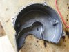
1st job was to gut the controller housing so that there is plenty of room for the new wiring.
The motor wire needs to have a MALE standard 9 pin julet on one end to simply connect to the female controller julet, the other end I cut to length before adding a hall wire connector (you can solder direct eventually) but first you need separate male/female connectors for the Blue, Green & Yellow halls for syncing the motor. Some controller have learn wires for this but KT's don't.
No pics for the phase soldering as it is the easy bit, there are some later showing the wiring before empty controller housing is placed in situ.
With the controller removed the phase bullet connectors to the drive side I left alone, the controller side bullets I cut the wire close to the old pcb and then soldered the coloured phase tails with bullets to the motor wire phases. Once done these simply push fit back together , you can solder directly however the bullets are handy for syncing the motor if you have to swap phases about. Before any soldering pass the motor wire end through the BBS grommet exiting the controller.
29.35£ 28% OFF|Okfeet KT Controller Electric Bicycle 36V 48V 22A Waterproof Sinewave Kunteng Controller Light Function for Ebike Conversion|Electric Bicycle Accessories| - AliExpress
Smarter Shopping, Better Living! Aliexpress.com
This I sourced from Ofkeet store on Aliexpress cost £36 and arrived in 14 days, no vat or duty.
1st job was to gut the controller housing so that there is plenty of room for the new wiring.
The motor wire needs to have a MALE standard 9 pin julet on one end to simply connect to the female controller julet, the other end I cut to length before adding a hall wire connector (you can solder direct eventually) but first you need separate male/female connectors for the Blue, Green & Yellow halls for syncing the motor. Some controller have learn wires for this but KT's don't.
No pics for the phase soldering as it is the easy bit, there are some later showing the wiring before empty controller housing is placed in situ.
With the controller removed the phase bullet connectors to the drive side I left alone, the controller side bullets I cut the wire close to the old pcb and then soldered the coloured phase tails with bullets to the motor wire phases. Once done these simply push fit back together , you can solder directly however the bullets are handy for syncing the motor if you have to swap phases about. Before any soldering pass the motor wire end through the BBS grommet exiting the controller.
Last edited:
The white 5 pin jst hall wire connector to the motor needs to be kept, 5 of the hall wires from the motor wire will need joining to the jst. The motor will want syncing so you will need to have M/F connectors first to do this, I used the standard J7061 hall block as I have a few spare.
Red & Black hall are easy they mate to the Red & Black BBS hall wires, the other BBS hall colours non stanadard being light Blue, White & Grey on the old pcb they are simply hall 3,2 & 1. These will connect to the thin Blue, Green & Yellow hall wires on the motor cable.
Whilst doing this job you need to cut the speed sensor wire close to the old pcb, this is left in place through the controller waterproofing grommet. The white wire is the signal wire so connects directly to the ninth wire (White hall wire) of the motor cable, the Red 5v you can solder to the motor wire Red hall and the Black Gnd wire to the Black motor hall wire.
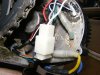
Motor White 5 pin hall connector with male pins soldered on, also speed sensor Red/5v & Black Gnd splice/soldered to motor hall 5v & gnd.
Temporarily I insulated the solder pin joint with tape to prevent a short should they touch as they will be close when finding the correct sync connection order later.
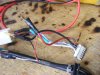
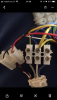
Motor wire with DJ7061 hall connector/female pins connected.
The male pins insulated are left out of the mating connector until wire order is tested ( there are 36 different combo's to try for perfect running). I tested all 36 combo's and only two worked correctly. White/Red & Black are easy they mate to self colour on the motor wire connections.
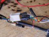
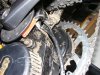
Motor wire and speed sensor wire from BBS with controller cover in stiu.
Red & Black hall are easy they mate to the Red & Black BBS hall wires, the other BBS hall colours non stanadard being light Blue, White & Grey on the old pcb they are simply hall 3,2 & 1. These will connect to the thin Blue, Green & Yellow hall wires on the motor cable.
Whilst doing this job you need to cut the speed sensor wire close to the old pcb, this is left in place through the controller waterproofing grommet. The white wire is the signal wire so connects directly to the ninth wire (White hall wire) of the motor cable, the Red 5v you can solder to the motor wire Red hall and the Black Gnd wire to the Black motor hall wire.
Motor White 5 pin hall connector with male pins soldered on, also speed sensor Red/5v & Black Gnd splice/soldered to motor hall 5v & gnd.
Temporarily I insulated the solder pin joint with tape to prevent a short should they touch as they will be close when finding the correct sync connection order later.
Motor wire with DJ7061 hall connector/female pins connected.
The male pins insulated are left out of the mating connector until wire order is tested ( there are 36 different combo's to try for perfect running). I tested all 36 combo's and only two worked correctly. White/Red & Black are easy they mate to self colour on the motor wire connections.
Motor wire and speed sensor wire from BBS with controller cover in stiu.
Last edited:
Having tested all 36 combo's and carrying out several battery disconnections and start up sequences, I'm happy that I have the best sequence for the wiring and finally fit the male pins in to the mating hall connector. At this stage the connector isn't necessary and directly soldering wires together and insulating is another option. The weak link is the hall connection via the 5 pin jst to the motor windings, I had two or three 03 hall errors on the lcd which was down to the connector backing out so I used a sealant to keep it in place.
The sequence that worked for me was;
Phase Blue/Blue, Green/Green & Yellow/Yellow.
Hall White/Blue, Lt Blue/Green & Grey/Yellow.
The other good sequence was;
Phase Blue/Yellow, Green/Blue & Yellow/Green.
Hall Lt Blue/Yellow, White/Green & Grey/Blue.
PAS is simple and the controller has a separate PAS julet connection.
10 pole PAS disc, this one is thin about 3mm.
Pas sensor/disc from underside.
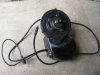
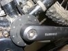
The donor bike is and old 17" Kona Blast with Rockshok air forks, drive is BBS01 with Kt 22a Ext controller. Gearing is double 32/48t chain ring and Alfine 8 with 20t sprocket.
Batteries used are PF 36v soft packs which I built and a pair of 36v Graphene 8ah Lipo's which T reconfigured permanently added a BMS to for simplicity.
Bike is dirty because I don't clean it as it will just get dirty again.
The sequence that worked for me was;
Phase Blue/Blue, Green/Green & Yellow/Yellow.
Hall White/Blue, Lt Blue/Green & Grey/Yellow.
The other good sequence was;
Phase Blue/Yellow, Green/Blue & Yellow/Green.
Hall Lt Blue/Yellow, White/Green & Grey/Blue.
PAS is simple and the controller has a separate PAS julet connection.
10 pole PAS disc, this one is thin about 3mm.
Pas sensor/disc from underside.
The donor bike is and old 17" Kona Blast with Rockshok air forks, drive is BBS01 with Kt 22a Ext controller. Gearing is double 32/48t chain ring and Alfine 8 with 20t sprocket.
Batteries used are PF 36v soft packs which I built and a pair of 36v Graphene 8ah Lipo's which T reconfigured permanently added a BMS to for simplicity.
Bike is dirty because I don't clean it as it will just get dirty again.
Last edited:
No load speed in PAS 5 is currently about 27mph with P1 value 86, I don't know the BBS01 motor ratio. To set P1 I will have to go out with my Garmin satnav to set this correctly so as to read the correct speedreading. PAS 5 showed about 696w on the screen using rear brake to draw current currently amps set to 20 via the lcd C5 setting.
Last edited:
Yep I arrived at the same sequenceThe sequence that worked for me was;
Phase Blue/Blue, Green/Green & Yellow/Yellow.
Hall White/Blue, Lt Blue/Green & Grey/Yellow.
You just need to keep an eye on the controller temperature. It can run much hotter than a typical hub motor because you can keep the current high for longer by using the gears. It's no problem if you don't use level 5 most of the time.
Heat is one thing I plan on keeping an eye out for, one reason why I opted for the 9 fet controller as I found the smaller 6 fets I have used can get massively hot.
PAS 5 I only save for hills and off road if needed so heat I think I can keep to minimum though will have to see how it goes. If necessary then a 5v fan mod will be used/incorporated later.
PAS 5 I only save for hills and off road if needed so heat I think I can keep to minimum though will have to see how it goes. If necessary then a 5v fan mod will be used/incorporated later.
Can you confirm that it runs OK at maximum crank rotation speed? Xiongda said that the reason they couldn't use the KT controller on their tiny motr was that it didn't have a high enough commuration speed. I can't remember the Xiongda's reduction ratio, but crank motors must have quite ahigh reduction too.
BTW, thanks for doing this. It all adds to the knowledge base.
BTW, thanks for doing this. It all adds to the knowledge base.
I have only had it up to speed (no load speed) on the bike stand, PAS5 on 48t/20t gearing.
Controller for the time I had it running appeared normal and no issue I found with running.
Gear calc syas 28.8mph is to whack I span it by hand at about 27.6mph.
I'm waiting to go on a test run but first need to repair my 'Bike Bag' that holds the batteries.
Tge 'Bike Bag' is a pannier type affair that straddles the top bar and can hold abut 40 - 50ah of batteries.
Jarob beat me to the mod and is also running a similar set up an don't recall him mentioning any ill effects, so assume all is well.
Back to square one with this one, only lasted 2.5 miles today before again I lost PAS and throttle so looks like the BBS01 isn't liking the KT or the motor is loosing drive, the same position I was in with the integrated controller.
Removed controller housing to access wiring and checked all was ok which is was and then went thru all the wiring combo's again this time not finding one that was suitable at all, even trying a few differing C2 phase values with the lcd 3.
Noticeably phase wiring got quite warm as did controller using some of the phase combo's.
The original combo that worked I could not replicate again.
I did find a phase/hall combo that initially worked then after switching lcd off then on a again, no dice so looks possibly compatibility with KT controller and lcd3 issue.
Hey Nealh , may I ask why do this mod ?
Is it case of why climb a mountain ?! Cos it's there !
Or is there a particular gain from using a non oem spec controller ?
I know you have had loads of issues with bbs controllers. Perhaps. that ? (I've really not had this. I blew one bbs02 controller but then I was rather taking the Michael with my settings and battery. I blame me entirely. Right now I have a 01 controller set to 350w matches to my 02 motor. Doesn't pull wheelies anymore but does keep the flab off my beer belly")
Is it case of why climb a mountain ?! Cos it's there !
Or is there a particular gain from using a non oem spec controller ?
I know you have had loads of issues with bbs controllers. Perhaps. that ? (I've really not had this. I blew one bbs02 controller but then I was rather taking the Michael with my settings and battery. I blame me entirely. Right now I have a 01 controller set to 350w matches to my 02 motor. Doesn't pull wheelies anymore but does keep the flab off my beer belly
BBS01 with internal controller had developed a PAS and throttle fault, no drive so thought can't be bothered no more and decided to try external controller route.
Think the original issue may have been needs a new PAS sensor and magnet.
I have never got on with it that well since day one and much prefer the no nonsense of hub drives/controllers which I have never had an issue with.
Problem is I can't hub drive the mtb as like you have Alfine 8, might have to get a GSM without controller to try. My thinking was no programming to faff with or set incorrectly just a simple 5 Pas KT with lcd3 and 5 pre set easy levels of current from13% - 100% with ability at a touch or two of a screen button to dial back current if needed.
Sorry to hear your having problems nealh
I’ve fitted kt controllers to 3 of my bikes: 2 x bbs01 and 1 bbs02
They’re all running great. I did 45 miles today on my commute with the bbs02 using the hailong battery base 9 fet controller, which I believe is 22a peak, emptying a 36v 17.5Ah battery twice in the process. The controller is set to max current all the time. I checked the temperature of the metal controller base at the end of each 22 mile run - feels about 40ish deg c, about the same as a 2a charger
The issue likely is within the BBS01 the only electronics left are the PAS pcb and the hall pcb a top of the windings. The phase/hall combo which matched the one you found doesn't play ball nor do any others now that are meaningful.
Tested the KT fets via the phases/ power supply wires and all ok.
Tested the KT fets via the phases/ power supply wires and all ok.
I wonder if you’ve actually just found the root cause which lead to the consequential failure of the original bbs01 controller - this time the more robust kt controller remains intact in the presence of the same faultThe issue likely is within the BBS01 the only electronics left are the PAS pcb and the hall pcb a top of the windings. The phase/hall combo which matched the one you found doesn't play ball nor do any others now that are meaningful.
Tested the KT fets via the phases/ power supply wires and all ok.
Related Articles
-
 Swytch announce new conversion kit with ‘pocket-sized’ battery
- Started by: Pedelecs
-
 New Swytch launches on Indiegogo, raises £100k in first hour
- Started by: Pedelecs
-
 Swytch to unveil 70% smaller, 50% lighter conversion kit
- Started by: Pedelecs