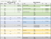
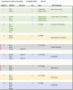
I have almost worked out the wiring for my controller, but not 100% certain it is right. Do you know if I have the correct connections?
I also have three wires from the battery connector that I am not sure where they go.
Bike is a Raleigh with the battery on the rear pannier with a front hub motor.
Thanks for taking a look.
I guess that you removed the plugs without marking them first. For the future, wrap some white insulation tape around the wires on both sides of a plug/socket connection and using a permanent marker, mark both, in your case, with the number from your list. Then disconnect them.
Another method, but slightly dangerous, is to note where a particular wire colour goes to a socket/plug, slip them out and put a piece of white or light grey heat shrink tubing over the wires, shrink it, then mark with a fine point permanent pen.
But making a mistake may prove costly!!!
The heat shrink tube must not grip tightly by the way, you can hold the middle with pliers and shrink just the ends, that will give you a better place in the middle for your mark!
Put a full stop by the 9 and the 6 to define them 100%.
Furthermore, you mention a plug 7, with regard to 6, but I see no 7 at all!
I agree with your marking of 1, 2, but no others completely 100%. Partly because I cannot see the pinning of plugs and sockets....
For instance, generally, but there is no uniformity or standard on e-bike electrics, plug 10 looks more like most bikes Hall effect to the motor, not the LCD display, but this is easily checked, you simply follow the cable back to source, it either goes forward, or backward on the bike. That will tell you.
Plugs 4,5 and 6, look more like the brake lever(s) sensor, they are often wired together. This will be a difficult one to prove either way, so you need to identify all the others to make sure!
Sometimes the brake levers are only one connector (seldom), but usually two, and the sockets are often linked.when there are two.
What 8 and 9 are (assuming they are identical for the moment, I have not got a clue. Hopefully they are pinned differently and that will help you further.
You have helped yourself to a great degree with your careful noting and clear focussed photos, and I am sure that someone else here will be able to help you far better that I can. Hopefully with exactly the same module.
Best wishes for an early fix and back to e-bike riding!!
regards
Andy

 489.5 KB Views: 14
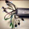 1.2 MB Views: 15