Controller help needed.

Neil5403

Pedelecer
Feb 5, 2017
213
16
Staffs, England ST15
Hi . My self build Specialised conversion has decided to die on me. The 48v battery seems ok, giving 51v to the controller. But nothing from there. Are there any serviceable parts inside the controller. The display attempts to come on for a fraction of a second when I first turn on then dead. So I should imagine it can only be the controller or a faulty display...
I do not want to wait a month for another controller from China. Seen some for sale on Amazon which would be a lot better but not exactly the same. Anyone know if I can get and try one from Uk, preferably Amazon for speed.
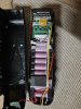
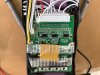
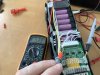
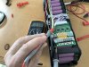
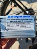
Photo of my controller.
48v rear hub q128c motor.
 

Attachments

vfr400

Esteemed Pedelecer
Jun 12, 2011
9,822
3,986
Basildon
51v isn't enough for a fully-charged 48v battery. It should be 54.6v.

The LCD works independently from the controller, so if it won't come on if either the battery, its connection or the LCd is faulty. Don't waste your money replacing the controller as it's unlikely that there's anything wrong with it.

How did the problem start? That will give a big clue to what's wrong.
 
Last edited:

Nealh

Esteemed Pedelecer
Aug 7, 2014
20,124
8,224
60
West Sx RH
Battery sounds like it is at fault, individual cell groups need checking for low voltage.
Are you up to opening the battery and using a meter to test/check.
 

Neil5403

Pedelecer
Feb 5, 2017
213
16
Staffs, England ST15
Battery sounds like it is at fault, individual cell groups need checking for low voltage.
Are you up to opening the battery and using a meter to test/check.
Yes. How do I do that.?
I put a test meter on the +&- from the battery to the controller and it registered 51.4v so I thought the battery was ok but if should be 54v then not ok!
It was working fine and then this week just dead.
 

Neil5403

Pedelecer
Feb 5, 2017
213
16
Staffs, England ST15
Yes. How do I do that.?
I put a test meter on the +&- from the battery to the controller and it registered 51.4v so I thought the battery was ok but if should be 54v then not ok!
It was working fine and then this week just dead.
Wouldn’t 51v be enough to get some life out of the controller or the screen? Surely the voltage would be lower than that when the battery is nearly flat and all works then...
Doesn’t the power for the screen come from the controller? Power from battery to controller and then out of controller to screen. So if the controller is duff, no power will get to the screen.
 
Last edited:

Nealh

Esteemed Pedelecer
Aug 7, 2014
20,124
8,224
60
West Sx RH
If one cell group is low then no the battery won't work, the internal BMS will notice the fault and shut down.
To check the cells one has to open the battery up to expose the BMS connector, the connector has multiple small thinner wires either 13 or 14 of them. One can then use this connector to get the individual voltages needed.
 

Neil5403

Pedelecer
Feb 5, 2017
213
16
Staffs, England ST15
Thanks.
I have opened up the battery and found the connector with lots of small white wires and one red one at one end. Do you know what reading they should be? If I plug my charger into the battery it stays green so no charge. Is that because the battery is not allowing it to charge? Still at 51.4v
 

vfr400

Esteemed Pedelecer
Jun 12, 2011
9,822
3,986
Basildon
Put your black probe where the black ground from the cell-pack attaches to the BMS, then with your red one, probe each of the little slots in the edge of the connector. write down the voltages, which should be incremental from one side to the other. You need 13 measurements starting at around 4.15V and increasing to 51.4v for the final one. If you end up about 4v short, then the last measurement comes from the red wire on the cell-pack.
 

Nealh

Esteemed Pedelecer
Aug 7, 2014
20,124
8,224
60
West Sx RH
Thanks.
I have opened up the battery and found the connector with lots of small white wires and one red one at one end. Do you know what reading they should be? If I plug my charger into the battery it stays green so no charge. Is that because the battery is not allowing it to charge? Still at 51.4v
Yes, the BMS is shutting down any charge. It is detecting a low cell group so likely one of them is below 3v - 3.1v.
 

Neil5403

Pedelecer
Feb 5, 2017
213
16
Staffs, England ST15
Yes, the BMS is shutting down any charge. It is detecting a low cell group so likely one of them is below 3v - 3.1v.
Thanks both. I will have a go tomorrow as my test meter need upgrading!
See pic below of battery opened.
If I record 51v coming from the battery, then why can’t it power the controller/display etc. Is the BMS also shutting the output down when I try to turn on display etc?D7D2DB91-E5F9-498B-9CA0-5544352EFA07.jpeg
 

Nealh

Esteemed Pedelecer
Aug 7, 2014
20,124
8,224
60
West Sx RH
The BMS is indeed not allowing any power thru so no power to the display.
The 1st wire Black is the 0v wire so place your Black probe on it and the Red probe on the #1 White wire to give a reading for cell group 1, it will be between 3.2v & 4.2v if ok.
Next place Black probe on White wire #1 and Red probe on White wire #2 this will give a reading for cell group 2.
Next place Black probe on White wire #2 and Red probe on White wire #3 this will give a reading for cell group 3.
Continue along the line until you have 13 individual cell group readings, you should find maybe one or two are below 3v or even lower.
The very last reading #13 will see the Black probe on the last White wire and the Red probe on the Red wire.
 

Neil5403

Pedelecer
Feb 5, 2017
213
16
Staffs, England ST15
The BMS is indeed not allowing any power thru so no power to the display.
The 1st wire Black is the 0v wire so place your Black probe on it and the Red probe on the #1 White wire to give a reading for cell group 1, it will be between 3.2v & 4.2v if ok.
Next place Black probe on White wire #1 and Red probe on White wire #2 this will give a reading for cell group 2.
Next place Black probe on White wire #2 and Red probe on White wire #3 this will give a reading for cell group 3.
Continue along the line until you have 13 individual cell group readings, you should find maybe one or two are below 3v or even lower.
The very last reading #13 will see the Black probe on the last White wire and the Red probe on the Red wire.
Great thanks for that I will give my results tomorrow. Are the cells replaceable if found to be faulty?
 

sjpt

Esteemed Pedelecer
Jun 8, 2018
3,669
2,673
Winchester
Great thanks for that I will give my results tomorrow. Are the cells replaceable if found to be faulty?
Nealh will give a fuller answer and may need to correct this, but a quick response.

It is not usually practicable to replace faulty cells. The battery and other cells are likely fairly old.

It is sometimes possible to recover individual cell groups that have dropped below critical voltage by charging just that group (to 4.2 v, or maybe a bit lower to match the voltage on the other non-faulty groups). Then the BMS will accept the entire battery.
 

Neil5403

Pedelecer
Feb 5, 2017
213
16
Staffs, England ST15
Nealh will give a fuller answer and may need to correct this, but a quick response.

It is not usually practicable to replace faulty cells. The battery and other cells are likely fairly old.

It is sometimes possible to recover individual cell groups that have dropped below critical voltage by charging just that group (to 4.2 v, or maybe a bit lower to match the voltage on the other non-faulty groups). Then the BMS will accept the entire battery.
interesting results!
I did as described above and all 13 readings were either 4.13 or 4.12.
I then measured the voltage from the positive terminal on the base of the battery to the 3 connections on the BMS. The bottom left was as before at 51.3 but the centre left (yellow) was 53.4 and the centre right was 53.8.
Does this mean the cells are ok and the problem is the BMS. Are they fixable or does it need changing if one can be sourced?
 

Attachments

vfr400

Esteemed Pedelecer
Jun 12, 2011
9,822
3,986
Basildon
interesting results!
I did as described above and all 13 readings were either 4.13 or 4.12.
I then measured the voltage from the positive terminal on the base of the battery to the 3 connections on the BMS. The bottom left was as before at 51.3 but the centre left (yellow) was 53.4 and the centre right was 53.8.
Does this mean the cells are ok and the problem is the BMS. Are they fixable or does it need changing if one can be sourced?
You're not measuring correctly. You should measure everything from the battery ground, which is the thick black wire connected to the cell-pack. That's the one marked B-, which by definition is 0v, so it can't be 53.8v, and the yellow one is probably C- (charge negative), which should also be 0v.

Measuring correctly might indicate where your problem lies, but what you have done shows that there is probably nothing wrong with your cells. If they were worn, I'd expect to see much more variation in the measured voltages.
 
Last edited:

Nealh

Esteemed Pedelecer
Aug 7, 2014
20,124
8,224
60
West Sx RH
B- on the BMS board or the B0 on the BMS connector will/should give the same readings, both grounds take off from the same point of the battery.
 

Nealh

Esteemed Pedelecer
Aug 7, 2014
20,124
8,224
60
West Sx RH
interesting results!
I did as described above and all 13 readings were either 4.13 or 4.12.
I then measured the voltage from the positive terminal on the base of the battery to the 3 connections on the BMS. The bottom left was as before at 51.3 but the centre left (yellow) was 53.4 and the centre right was 53.8.
Does this mean the cells are ok and the problem is the BMS. Are they fixable or does it need changing if one can be sourced?
Was the BMS connector in or out when you took the 51.3 measurement ?
 

Neil5403

Pedelecer
Feb 5, 2017
213
16
Staffs, England ST15
Was the BMS connector in or out when you took the 51.3 measurement ?
Connector was in. 0v when out.
I am giving the readings when the positive is connected to the base of the battery where is attatches to the frame caddy. I appreciate they are grounds but odd that they give different readings when a circuit is made with the positive.
Pictures below are from the positive on the ribbon connector. Same readings.
All 3 negatives read 0v
 

Attachments

Last edited:

Nealh

Esteemed Pedelecer
Aug 7, 2014
20,124
8,224
60
West Sx RH
The two thin White wires next to the Yellow/C-, are they for temp sensor or switch ?