CST - it's all working

103Alex1

Esteemed Pedelecer
Sep 29, 2012
2,228
67
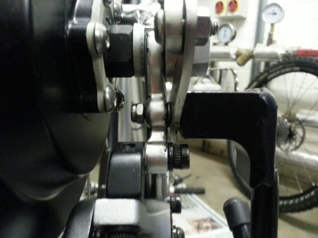
FINALLY ... got my ducks in a row ... rigged up the torque arm and checked final setup as it will be on finished bike. Bolt is exactly the right size.

so .....

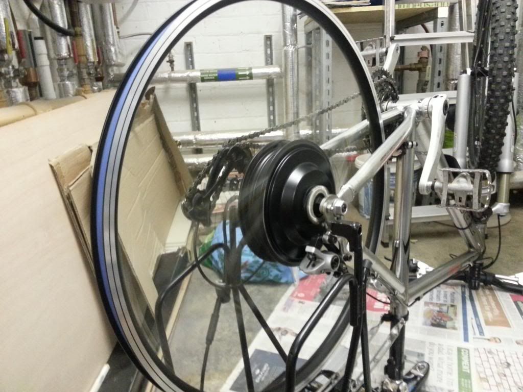
bike upside down, throttle connected to controller, battery connected to controller and controller to motor with Hall Sensor pins poked in to the female socket ...

and ....

IT WORKS. Incredible spin from the motor. Really quiet too. Amazing. First time seeing it actually working since I got it about 2 1/2 weeks ago.

Very excited now and really heartened as it's been quite a journey for me to get this far.... and one which I would never have had a hope of getting to grips with without constant help from d8veh in particular and the other helpful input on this forum so far. THANK YOU.

Loads more work to do to get all the plans into play but this at least means the kit's good to go.

All secure and ready to spin (well, I need to tighten that pivot bolt but apart from that) ...


Spin city ....


Everything looks rock solid on the dropouts, axle and torque arm. I think that side of things is all good to go now :D

Happy is an understatement - and I haven't even got a tyre on yet or connectors on all the contacts. Big rush of encouragement from this. Happy boy tonight :cool:
 

NRG

Esteemed Pedelecer
Oct 6, 2009
2,592
10
Congratulations! :cool:
 
D

Deleted member 4366

Guest
I can remember how I felt when my first one sprang to life. It's been a bit of a journey and still a bit of a way to go, but what you'll learn from this project will give you a good understanding of all things ebike, which will inform your choices in the future.
 

oigoi

Esteemed Pedelecer
Apr 14, 2011
467
7
Really good to see it all going working.There are problems and trials that come along in the process of building a bike yourself but if you can make it through and get it to work you learn so much along the way. Then in the future you are in a much stronger position if anything goes wrong and are more able to sort things out yourself
 

103Alex1

Esteemed Pedelecer
Sep 29, 2012
2,228
67
Is the best way to test speed / RPM to put a cycle computer on it or is there some other gadget people use for this ?
 
D

Deleted member 4366

Guest
Is the best way to test speed / RPM to put a cycle computer on it or is there some other gadget people use for this ?
A normal cycle computer should work, but don't forget to set the wheel size to 26 x 1.95 or whatever.
When you're checking the speed, do it normally first, then unless you have the actual three-speed switch, take a small piece of wire with the ends stripped, put one end in the middle hole of the three-speed switch connector and the other end in each of the outer holes in turn. One way, should make it go faster and the other way slower. Can you give us the speed results? When I did it on my 350w CST, it span up to 33mph, but I never checked the 500w one. I have the speed sensor on my front wheel, so can't check now.
 

103Alex1

Esteemed Pedelecer
Sep 29, 2012
2,228
67
OK great and yes, will do. I don't own a cycle computer yet so another thing to add to the shopping list (!). Can I fit one to the front and the other to the back if I later get a Speedict ? Presume I need 2 sensors, one each for the Speedict and the cycle computer as alternatives - so I can have the regular speedo going if I don't take my mobile phone (I leave it at home if I go off to the beach ..)

Does the Speedict one go on the front wheel ? If so, will probably buy a remote one to fit on the back wheel for the regular cycle computer.

Edit - I have the actual 3-speed switch so can use that I guess ... ordered a bunch of accessories from BMS with the main parts 'just in case' ;)
 
Last edited:

Old_Dave

Esteemed Pedelecer
Sep 15, 2012
1,211
2
Dumfries & Galloway
The Speedict sensor is a bog standard wired reed switch.. which is fitted to the wheel that's closest to where the Speedict device is going to be located, so ii your sensor was modded / fitted with a servo style plug and socket it could be used for either a std computer or the Speedict


Sent from my iPhone using Tapatalk
 

103Alex1

Esteemed Pedelecer
Sep 29, 2012
2,228
67
The Speedict sensor is a bog standard wired reed switch.. which is fitted to the wheel that's closest to where the Speedict device is going to be located, so ii your sensor was modded / fitted with a servo style plug and socket it could be used for either a std computer or the Speedict


Sent from my iPhone using Tapatalk
Mmkay .... dunno what any of that means tbh lol... in basic terms can I have one sensor installed that will run either Speedict or cycle computer (or both together) without having to take things off and put them back on again to switch between (which would be regular) ?
 

Old_Dave

Esteemed Pedelecer
Sep 15, 2012
1,211
2
Dumfries & Galloway
Mmkay ....
As in Southpark ?

can I have one sensor installed that will run either Speedict or cycle computer
Yes

(or both together)
No

The method would be to cut the sensor wire and fit a little plug and socket so that it could either plug into the speedict or your bike computer (I can point you at the right plug & socket if you decide you want them)
 

103Alex1

Esteemed Pedelecer
Sep 29, 2012
2,228
67
As in Southpark ?
Yep.

:D

:(

The method would be to cut the sensor wire and fit a little plug and socket so that it could either plug into the speedict or your bike computer (I can point you at the right plug & socket if you decide you want them)
OK I understand that ... and thanks on the connectors - seem to have spent more time investigating connectors and switches recently than working on the bike lol. I'd better check back when I find a cycle computer I want then I guess and we can check it's compatible with being modded like this ?

If both computer and Speedict came with a sensor I am guessing I could install the Cycle Computer sensor on this build and use the one from the Speedict (if I get one and when it then arrives... ) on a non-eBike to allow the CC to be swapped between the 2 bikes... is that right ? Interchangeable accessories / parts always make a lot of sense :cool:

Blimey ... so much to think about all at once - my little head is spinning ! :eek:
 
Last edited:
D

Deleted member 4366

Guest
It's a two minute job to move a Cycle computer from the back wheel to the front wheel. Get a cycle computer from Tescos for £6.96. They're always handy. Put it on the back wheel, and then you can start testing. When you've finished testing, you can move it to the front of the bike. If you decide on a Speedict, you can transfer the Tesco one to another bike. It's not practical to transfer sensors between bikes. When you put the sensor on the back, you normally have to put a block under it to get it close enough to the magnet. To save time, don't use the cable ties. You can tape it in place or even hold it in your hand. I usually hold it approximately next to the magnet, and then spin up the wheel and move the sensor in position to get a speed reading, so the only thing to install is the magnet, which takes about 10 seconds.
 

hech

Esteemed Pedelecer
Oct 29, 2011
352
27
argyll
Well done Alex it's been an epic build but well worth it I'm sure. Now all you have to do is write the review!:)
 

103Alex1

Esteemed Pedelecer
Sep 29, 2012
2,228
67
It's a two minute job to move a Cycle computer from the back wheel to the front wheel. Get a cycle computer from Tescos for £6.96. They're always handy. Put it on the back wheel, and then you can start testing. When you've finished testing, you can move it to the front of the bike. If you decide on a Speedict, you can transfer the Tesco one to another bike. It's not practical to transfer sensors between bikes. When you put the sensor on the back, you normally have to put a block under it to get it close enough to the magnet. To save time, don't use the cable ties. You can tape it in place or even hold it in your hand. I usually hold it approximately next to the magnet, and then spin up the wheel and move the sensor in position to get a speed reading, so the only thing to install is the magnet, which takes about 10 seconds.
Ah. Should be able to get one in by the end of the week then hopefully and rig up easily to test.

The idea wasn't to move the sensor between bikes it was to have one sensor installed compatible with either Speedict or Cycle computer on Bike 1 and the other sensor compatible just with Cycle Computer installed permanently on Bike 2. Using Old_Dave's adaptor on Bike 1 can switch between plugging in Speedict for Speedo when out with phone or cheap cycle computer when not.

There are times when even if I install Speedict I won't have my phone with me on this Build Bike but will be nice to have a basic cycle computer instead, so I only risk that and not a £350 phone getting nicked from my bag when I am in the sea lol.

It's all these things you have to think about and plan in when you have to leave all your stuff unattended on the rocks. Or if you have a car you bury your electronic car key and leave a marker because otherwise it inevitably gets lost/water damaged and won't start the car (I have lost 3 hire car keys and 2 of my own to Neptune in the last couple of years at great consequential expense :rolleyes:). Surfers and divers understand these things but they seem completely bonkers to the rest of the world ;)

Well done Alex it's been an epic build but well worth it I'm sure. Now all you have to do is write the review!:)
Cheers, hech. I do get there eventually ! A lot of bells & whistles might be going on the bike from here so I'll hold off a wee bit longer :)
 
Last edited:

103Alex1

Esteemed Pedelecer
Sep 29, 2012
2,228
67
A normal cycle computer should work, but don't forget to set the wheel size to 26 x 1.95 or whatever.
When you're checking the speed, do it normally first, then unless you have the actual three-speed switch, take a small piece of wire with the ends stripped, put one end in the middle hole of the three-speed switch connector and the other end in each of the outer holes in turn. One way, should make it go faster and the other way slower. Can you give us the speed results? When I did it on my 350w CST, it span up to 33mph, but I never checked the 500w one. I have the speed sensor on my front wheel, so can't check now.
Cycle computer finally turned up so have done some tests. Magnet mounted 80mm down spoke on rear wheel (it doesn't say anything about siting and how this might affect rpm count if at all).

Wheel factor used 2124 (700 x 25C) gives 26.1mph on normal and 2073 (650A) gives 25.5mph

I poked in the pins of the 3-speed switch and tried it ... the coulors don't match up though - there are 2 blacks and 2 blues on both the controller socket and attached to the switch pins, and then the red wire on the switch is only left with a green on the controller socket to pair to :confused: .. paired connection at the bottom of the pic here :

20130209_133854[1].jpg

Connecting up this way gave about 1mph difference with speed readings between 25.7 and 26.3mph but no significant variances.

I joined the 'speed limiter' wires on the controller (the two white ones) to see what effect that had - speed reading was a steady 20.1mph.

So not sure what's up with the 3-speed switch thing ?
 
Last edited:
D

Deleted member 4366

Guest
Those three speed switches are an absolute mystery to me. You get a different result on every motor/controller combination. It looks like you wired it correctly. You could try what I suggested above in case the switch wiring is faulty. Use a piece of wire to join the middle to each of the two sides in turn to see if it has any effect.

The speed seems about right for 700C wheels. We get about 22 mph max on the flat with 26" wheels.
 

103Alex1

Esteemed Pedelecer
Sep 29, 2012
2,228
67
OK I'll give that a go. The wheel size settings were off the instructions - 700-25C being 26.5" and 650A being 26". The sticker on the rim said 26" x 1.5. Didn't seem to make more than 1mph difference between the two settings.

I'll try to get back down to do the wire test and see what difference that makes (if any) before I go, if I can. Should be back by Wednesday or Thursday next week but might be away a bit longer depending on how things go.
 

103Alex1

Esteemed Pedelecer
Sep 29, 2012
2,228
67
You could try what I suggested above in case the switch wiring is faulty. Use a piece of wire to join the middle to each of the two sides in turn to see if it has any effect.
Test done and here are the results :

Wire poked into holes with black (middle) and blue wires coming from connector - 21.5mph

Wire poked into holes with black (middle) and green wires coming from connector - 26.7mph

Re-test with 3-spd connector not used - 25.5mph

Re-test with speed limiter connected - 20.1mph

Hope that means something helpful. Might be time for me to search out your cruise control postings and look into that :).
 
D

Deleted member 4366

Guest
I've now discovered that the best and cheapest cruise control is with an additional small thumb throttle and a three position switch. You already have the switch. You splice together the red and black wires near the handlebars and cut the white signal wire from the normal throttle. Then you solder the white signal wires to the outer two pins on the switch, and the middle pin to the other end of the cut white wire that coes to the controller. Like this, but with a second throttle instead of a potentiometer. The white wires are shown as green.
potmod.jpg Photo by d8veh | Photobucket
 

103Alex1

Esteemed Pedelecer
Sep 29, 2012
2,228
67
I've now discovered that the best and cheapest cruise control is with an additional small thumb throttle and a three position switch. You already have the switch. You splice together the red and black wires near the handlebars and cut the white signal wire from the normal throttle. Then you solder the white signal wires to the outer two pins on the switch, and the middle pin to the other end of the cut white wire that coes to the controller. Like this, but with a second throttle instead of a potentiometer. The white wires are shown as green.

potmod.jpg Photo by d8veh | Photobucket
How does the cruise control actually function, Dave ? Do you mount both throttles on the handlebars left & right sides, say ? Then I'm a bit puzzled how they actually work ...

Absolute basics as haven't ever actually used one on the road - if I fit one thumb throttle then I can depress it as much as I like for a speed range of zero to max speed controller allows, but downside is I have to hold it in position to maintain a speed and that can be difficult when changing gear for example.

If I fit a 3-spd switch all I'm doing is having different ranges of min/max speeds for the travel range of the throttle (?) but still have more / less power and hence more / less speed depending on how far I depress the throttle ?

I then splice in the 2nd throttle as above. Let's say I'm at 15mph and want to cruise at that speed without having to hold a throttle down to sustain it. Does simply depressing the 2nd throttle trigger the 'speed hold' and then I let go of both throttles ?

Presumably the cruise control is disengaged after I either brake or re-depress the main throttle (just what my logic would assume but not sure how this marries in to the wiring / controller array) or is there some other way the device works ?

... or have I got that wrong ?
 
Last edited:

Advertisers