eBike Brake Wiring Question

Powerclocks

Finding my (electric) wheels
Sep 18, 2020
18
2
71
Australia
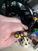
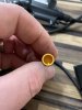
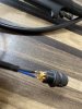
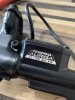
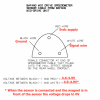
Hi, I am fitting new bafang brake levers to my bike. I aso bought myself a new controller, it should be here soon, I wanted to fit Brake Switches so I bought the Bafang brake levers with 3 pin Julet plugs x 2 new and a throttle control, all part of my upgrade, I have the throttle and the brake handles fitted up on the handlebars with a bit of modification, my next question is about wiring, I looked at the wiring diagram for the controller and it appears to be a two wire input, I had not noticed that before, refer to the the wiring diagram, it shows as follows:-
1. Low potential brake signal
2. Black Grnd.
below that I see
1. Green recognition motor phase
Firstly can I use the three wire switches to hook into this controller or did I waste my money
If I can use them how do I do it?.
I see the diagram allows the two sets of brake wires wires to be joined, would the three wires be similarly joined and where to?
I appreciate the input from anyone with experience in this stuff.
 

Attachments

vfr400

Esteemed Pedelecer
Jun 12, 2011
9,822
3,986
Basildon
I would cut the connector off the brake to expose the wires, then it should be obvious which is which by the colours. They all need to be connected to the controller. The signal and ground wires go to the 2-wire brake connector on the controller and you need to provide a 5v by splicing a wire onto any 5v, like the red on the throttle, PAS or hall sensors.

If you have the pair of green self-learning wires, you will need to do the self-learning procedure, then disconnect them.
 

Nealh

Esteemed Pedelecer
Aug 7, 2014
20,125
8,225
60
West Sx RH
The Bafang moulded connectors are likely Higo rather then Julet (take a close look to read) Higo's wire sequence is different to Julet though both are compatible fit wise.
If I remember correctly the pin out opposite the Higo lug/nick locater (Gnd) is the same sequence and the other two wire are reversed compared to Julet.
 
  • Like
Reactions: Rooneydog

jokskot

Pedelecer
Jul 14, 2018
156
47
75
I would cut the connector off the brake to expose the wires, then it should be obvious which is which by the colours. They all need to be connected to the controller. The signal and ground wires go to the 2-wire brake connector on the controller and you need to provide a 5v by splicing a wire onto any 5v, like the red on the throttle, PAS or hall sensors.

If you have the pair of green self-learning wires, you will need to do the self-learning procedure, then disconnect them.
I'm not sure that vfr400 is correct here. By all means try his recommendation but if the solution does not work, repost and I'll offer an alternative approach.
 

vfr400

Esteemed Pedelecer
Jun 12, 2011
9,822
3,986
Basildon
I'm not sure that vfr400 is correct here. By all means try his recommendation but if the solution does not work, repost and I'll offer an alternative approach.
I'm sure I'm right as I've done it loads of times.Say what you think the problem is, so I can put you at ease.
 

Powerclocks

Finding my (electric) wheels
Sep 18, 2020
18
2
71
Australia
Thanks for that, I hope to sort it out before the controller unit arrives, I did look the wiring diagram over and ticked off the compatible wires to the existing loom, once all are accounted for I will get new plugs from Jaycar and it should be a quick hook up, (I hope).

I will get used to it, it will just take a little time to adjust to electronics. Fitting the throttle to pas and adding the brake sensors are the only modifications.

I am only being persistent on this particular bike as I liked the name, iZip (and it was pristine, old and cheap), I also have a Vintage 1992 Aero Racing Bicycle.
A nicely restored ZIPP 2001 (made in 1992) and want the two of them in the Stable for fun and pleasure. These are a very sought after bicycles and the two will look great together though they are unrelated in manufacture.
 

vfr400

Esteemed Pedelecer
Jun 12, 2011
9,822
3,986
Basildon
Thanks for that, I hope to sort it out before the controller unit arrives, I did look the wiring diagram over and ticked off the compatible wires to the existing loom, once all are accounted for I will get new plugs from Jaycar and it should be a quick hook up, (I hope).

I will get used to it, it will just take a little time to adjust to electronics. Fitting the throttle to pas and adding the brake sensors are the only modifications.

I am only being persistent on this particular bike as I liked the name, iZip (and it was pristine, old and cheap), I also have a Vintage 1992 Aero Racing Bicycle.
A nicely restored ZIPP 2001 (made in 1992) and want the two of them in the Stable for fun and pleasure. These are a very sought after bicycles and the two will look great together though they are unrelated in manufacture.
Just to add to what I wrote above, to connect a three wire brake switch to a 2-wire connector, the two wires are signal and ground. They must be connected the right way round with ground to ground and signal to signal, then you can add the 5v to the third wire. If you need help identifying which wire is which, post again.
 
  • Like
Reactions: Rooneydog

Rooneydog

Finding my (electric) wheels
Feb 26, 2022
9
1
Lake District UK
New here so hi everyone :)

I’m currently building a ebike.
GT Avalanche 2.0 hydraulic brake 2010 bike. Bafang bbs02 750w 17.5ah down the tube battery.
Looking to install Tektro Auriga eSUB Hydraulic levers rather than gluing the Bafang sensors.

So it’s the Bafang loom from controller is 3 pin and the tektro has 2 wire black and blue.

is it possible this can be wired to work?

Sorry if this has been posted else where.
 

Attachments

Last edited:

Nealh

Esteemed Pedelecer
Aug 7, 2014
20,125
8,225
60
West Sx RH
The 2 pin is a Reed sensor so doesn't use the 5v, the 3 pin is Hall sensor and does use the 5v. One can try just hooking up the two wire to see if they will work.

Bafang use Higo I don't know the wire sequence as they differ from the similar looking Julet ones.
 
  • Like
Reactions: Rooneydog

guerney

Esteemed Pedelecer
Sep 7, 2021
10,197
2,996
I don't know, and the following is pure speculation on my part - but at one point (to ascertain whether my controller was fried) for testing purposes, the seller of my kit sent me this diagram of the speed sensor connector, so maybe one of the three wires from the brake could be a necessary signal wire?


45892
 
Last edited:
  • Like
Reactions: Rooneydog

Nealh

Esteemed Pedelecer
Aug 7, 2014
20,125
8,225
60
West Sx RH
The Higo 3 pin brake and speed sensor use the same 3 pin connector so wiring will be the same, if one can wire the two wire brake to the Gnd & Sig on the controller side then one can test the effectiveness of the brake sensor.

From the Tektro the Black/Gnd and Blue Signal.
 

Rooneydog

Finding my (electric) wheels
Feb 26, 2022
9
1
Lake District UK
The 2 pin is a Reed sensor so doesn't use the 5v, the 3 pin is Hall sensor and does use the 5v. One can try just hooking up the two wire to see if they will work.

Bafang use Higo I don't know the wire sequence as they differ from the similar looking Julet ones.
 

Nealh

Esteemed Pedelecer
Aug 7, 2014
20,125
8,225
60
West Sx RH
Fished bike LOL

Finished the bike.
My pc is like that what you type doesn't always come out looking right and one doesn't notice it till later or someone say's o_O .
 
  • :D
Reactions: PC2017

PC2017

Esteemed Pedelecer
Sep 19, 2017
1,306
330
Scunthorpe
Finished the bike.
Assuming there is meant to be a picy of some sort... Pop a picy on this thread, the link you provided just re-links this thread lol