I recently bought a D2s and so far I am very pleased. However I am concerned that it has no "Ignition Switch". Anyone in the know could turn the system on whilst I was away from the locked up bike in town. I intend putting in a key-switch to disable the system.
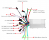
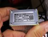
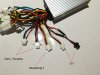
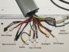
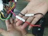
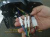
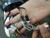
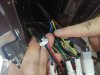
I have checked out the controller wiring and proved all of the connection but for two, an orange and black connection, and a red- black-yellow connection. Can anyone tell me what these could be for? The controller is marked as WK3615YS.
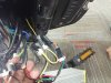
I have "enclosed" the open area below the controller with plastic panels. I will mount the key-switch here.
Richard
I have checked out the controller wiring and proved all of the connection but for two, an orange and black connection, and a red- black-yellow connection. Can anyone tell me what these could be for? The controller is marked as WK3615YS.
I have "enclosed" the open area below the controller with plastic panels. I will mount the key-switch here.
Richard