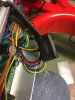
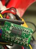
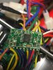
On opening my controller there is a small PCB under shrink wrap that appears to be connected to the lighting output. What is on that PCB is a mystery but I am guessing the transistor you mention.
My idea was to use the light output wire as the low voltage side of an optical relay as per the ES thread I linked above and use 12v from a DC/DC converter to power the lights. As I want to also be able to ride my trike with the motor wheel removed the lighting circuit will optionally be powered by a 3S 5000 mAh Lipo brick.
Projected are:
- always on head and tail lights
- brake light, nothing fancy, just a second rear LED light that is turned on by the brake sensors (possibly mounted high up for SUV's...)
- indicators, mostly useful in "warning" mode - all flashing for riding in town where there are no cycle paths but a motorcycle turn signal, switch will be mounted too
- hi/lo beam headlights, again nothing fancy just a second headlight adding 70-80 lux when on the open road. This is the one I want to be able to turn on from the controller button.

 MTF Enterprises announces acquisition of EMU Electric Bikes
 Wisper 806T folding bike wins Which? ‘Best Buy’
 Sustrans calls for protected cycle lanes
 Amazon launch their first UK e-cargo micromobility hub