First, I must compliment you on your work up to now, always good to "have go".
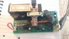
But sadly, I have to agree with another poster here, that its unlikely that the MOSFETs will have survived....and diodes, some polarised caps will also taken a "hit!". Even if not YET defective, they may be "weakened" and fail a few weeks later....
So before you invest in much time, may I suggest that you simply replace the controller with an identical one, if possible. Sorry to be negative....
Simply replace with a new controller, one with an LCD from say ebay....They cost from about 30 UK pounds upwards.
Maybe someone here has done that already and can give some good advice?
But before you do that, also get the motor Hall effect sensors checked out, as they can also get damaged, far less likely, but still possible, as they are a voltage sensitive device.
This video may help further in understanding them:-

www.pandaebikes.com
The next video shows testing and how to replace them, but you should be able to test them where they connect to the controller unit, its often a 6 wire white plastic connector block. Hopefully, there is enough residual magnetism in the rotor to switch them, but I have never tested that myself in that way, only with an external magnet! In this video he talks about "welding", he means "soldering"....
Remember:-
Some 3 phase motors do not have them anyway, because:-
Some controllers do not need them!
And some motors are brushed and do not have them either....though seldom brushed IMHO on modern e-bikes.
Most motors today are technically basically a 3 phase AC motor, but designed for switched 3 phase low voltage DC....
Just some thoughts, but some others here will have already done what you need to do, listen to them carefully.
regards
Andy

 2.2 MB Views: 18
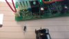 2.1 MB Views: 19
 2.1 MB Views: 18
 3.1 MB Views: 16


