Hi all,
I picked up a great value eMate a few weeks ago as an unwanted PX at a local bike shop - they said the battery had been fixed as it was dead at trade-in. It's cut out on me 3 times in 335 miles, each time in heavy rain, and it always came back after a minute or two off, until this morning.
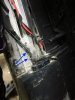
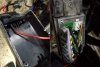
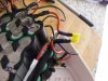
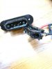
Went round all the connectors with WD40 and a cloth, but nothing got it working again. Spent 30 minutes trying to remove the battery, and when I unscrewed the two halves found that the power feed into the controller had been superglued in place...
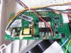
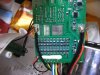
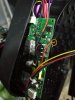
Going over things with a multimeter the battery pack does have 30+ volts in it, but looking more closely at the board (BMS ?) it seems like a red sense wire has come off (yellow circle) and I am wondering if it came from the empty solder pad in the purple circle:
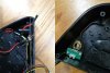
I think the power switch board uses the disconnected red wire, but I'm a bit puzzled as there's still a voltage at the exit pins into the controller box under the battery but no amount of button pressing gets the LCD to come on.
Does that floating wire do anything more than light up the LEDs on the battery pack ? If so, then that's never worked the entire time I've had the bike (those lights have always been off).
Any and all advice most welcome, as this bike is too much fun to leave in the garage, but I'm not sure where to start digging next.
I picked up a great value eMate a few weeks ago as an unwanted PX at a local bike shop - they said the battery had been fixed as it was dead at trade-in. It's cut out on me 3 times in 335 miles, each time in heavy rain, and it always came back after a minute or two off, until this morning.
Went round all the connectors with WD40 and a cloth, but nothing got it working again. Spent 30 minutes trying to remove the battery, and when I unscrewed the two halves found that the power feed into the controller had been superglued in place...
Going over things with a multimeter the battery pack does have 30+ volts in it, but looking more closely at the board (BMS ?) it seems like a red sense wire has come off (yellow circle) and I am wondering if it came from the empty solder pad in the purple circle:
I think the power switch board uses the disconnected red wire, but I'm a bit puzzled as there's still a voltage at the exit pins into the controller box under the battery but no amount of button pressing gets the LCD to come on.
Does that floating wire do anything more than light up the LEDs on the battery pack ? If so, then that's never worked the entire time I've had the bike (those lights have always been off).
Any and all advice most welcome, as this bike is too much fun to leave in the garage, but I'm not sure where to start digging next.