Hello,
Few months ago I asked for help with converting my bicycle to an ebike on this forum. After a bunch of discussion and research, I selected all components, purchased them, and installed the parts over the Christmas and New Year's break. Now I want to show and describe the conversion, in case anyone is interested or has questions.
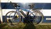
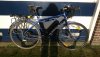
My bicycle is 2013 Kona Sutra. I bought it new 5 years ago. Pretty much all parts on the bicycle were original except the rear rack. I already used the bicycle for commuting to work around 18 km each way but I wanted to shorten the commuting time and was often frustrated with wind lengthening my commute and sucking up all of my energy. Kona Sutra is absolutely perfect for commuting, it is reliable, can carry panniers, shifting is perfect, brakes are great, has adequate crankset 48-36-26, stable on the road. I wanted to make minimal changes to the bicycle so I selected a kit that allowed me to do this and make me go fast. Since I live in Netherlands, the commute is all flat and all of it is on bicycle paths but there is a fair bit of wind.
Parts I selected:
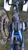
First small issue was that the rear brake disc caliper was slightly touching the motor. To fix this I took off the caliper completely and put one thick washer between the caliper and caliper mounting part. This raised the caliper just enough so it does not touch the motor. So caliper is slightly angled comparing to the way it was originally but this does not affect the braking ability or the alignment of the caliper.
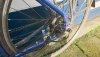
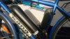
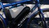
Second small issue was that the battery mounting bracket had holes for mounting bolts in a position that made the bracket and battery impossible to fit on the frame. The holes were too high on the mounting bracket. So I had to drill two new holes lower than the original ones. It didn't take long. After that battery fit perfectly.
Third small issue was that the hidden wire brake sensors were getting stuck. This was really just a problem with the brake cables. Brake cables were old and come strands of wire came loose. So I bought new brake cables for both brakes, new cable protectors, removed all cables, installed new cables with new cable protectors, then installed brake sensors. After this, brakes worked perfectly and brake sensors worked perfectly.
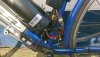
Fourth issue was that PAS sensor came with a waterproof Julet connector and the controller had JST conector input. I had to cut off the Julet connector, I cut off one of the unused JST male connectors and solder spliced wires to make a new connector for the PAS.
Fifth issue (or more annoyance) was the wiring. It was too bunched up, too long, and bullet connectors were used for battery and motor phase connections. Eventually I ended up shortening two brake sensor cables, shortened the motor phase and motor hall sensor cables, cut off the bullet connectors, installed XT60 for two battery connections, and installed MT60 for three motor phase connections. All of this was done with soldering and solder splicing. Changing the battery bullet connectors to XT60 was especially useful because the way the battery was initially connected to the controller forced me to always disconnect the nice battery metal connector at the battery input every time I wanted to remove the battery for charging or storage. Now I leave the nice metal battery connector always connected to the battery and I detach at the XT60 connector.
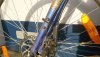
Also for the wiring I used some cable wrap to protect the LCD3 and one brake sensor cables during routing. Then I used excellent self-fusing tape (Tesa Extra Power Repair Tape) for wrapping all connectors to protect them from elements. This tape is excellent, I highly recommend it. It is waterproof, huge temperature extremes, and it seals nicely. You cannot tape it to anything except itself. It only tapes to itself.
Sixth issue was the speed reading. That was solved with help of Nealh and forum posts. It was all in the LCD3 settings.
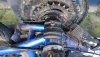
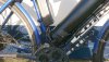
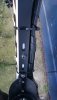
Final issue was for me the most frustrating one but it was really an easy fix. After everything was finally put together and I was cycling with the bike, I kept having motor cut outs. Long story short, it was the PAS. Initially I installed it incorrectly over the cable guide, below the bottom bracket. What I had to do was remove the cable guide for the derailleur cables, install the sensor against the frame, install a new cable guide that came with the sensor, put cover over the whole thing that came with the sensor, and tighten everything. I also had to move the PAS super close to the magnet ring, so close that it looks like it is touching. Once I did this, I tested it while the bike was upside down and I noticed that if the PAS is not close enough to the ring, it was giving intermittent signal. Once it was close enough, I tightened everything and tested it. I had no more problems with motor cutting out. Now it runs perfectly!
My LCD3 settings are:
Max speed = 45 km/h; Wheel size = 700c;
P1 = 212; P2 = 1; P3 = 1; P4 = 1; P5 = 15;
C1 = 7; C2 = 0; C3 = 0; C4 = 0; C5 = 7; C6 = 3; C7 = 0; C8 = 0; C9 = 0; C10 = n; C11 = 0; C12 = 4; C13 = 0; C14 = 2.
Here are some photos.
Few months ago I asked for help with converting my bicycle to an ebike on this forum. After a bunch of discussion and research, I selected all components, purchased them, and installed the parts over the Christmas and New Year's break. Now I want to show and describe the conversion, in case anyone is interested or has questions.
My bicycle is 2013 Kona Sutra. I bought it new 5 years ago. Pretty much all parts on the bicycle were original except the rear rack. I already used the bicycle for commuting to work around 18 km each way but I wanted to shorten the commuting time and was often frustrated with wind lengthening my commute and sucking up all of my energy. Kona Sutra is absolutely perfect for commuting, it is reliable, can carry panniers, shifting is perfect, brakes are great, has adequate crankset 48-36-26, stable on the road. I wanted to make minimal changes to the bicycle so I selected a kit that allowed me to do this and make me go fast. Since I live in Netherlands, the commute is all flat and all of it is on bicycle paths but there is a fair bit of wind.
Parts I selected:
- Q128C 48V 328 rpm rear hub motor with the 700c wheel (BMS Battery)
- Kunteng KT36/48SVPR-20A controller (20A max current, 10A nominal) (PSWPower)
- Kunteng KT LCD3 (PSWPower)
- 48V 12.8Ah bottle battery with maximum discharge current of 30A (PSWPower, free shipping and free tax from Germany)
- King Meter KM-DISC17, 12 magnet split ring, right side (ATMParts.eu)
- King Meter KM-T281-R right side PAS (ATMParts.eu)
- 2x hidden wire brake sensors (PSWPower)
First small issue was that the rear brake disc caliper was slightly touching the motor. To fix this I took off the caliper completely and put one thick washer between the caliper and caliper mounting part. This raised the caliper just enough so it does not touch the motor. So caliper is slightly angled comparing to the way it was originally but this does not affect the braking ability or the alignment of the caliper.
Second small issue was that the battery mounting bracket had holes for mounting bolts in a position that made the bracket and battery impossible to fit on the frame. The holes were too high on the mounting bracket. So I had to drill two new holes lower than the original ones. It didn't take long. After that battery fit perfectly.
Third small issue was that the hidden wire brake sensors were getting stuck. This was really just a problem with the brake cables. Brake cables were old and come strands of wire came loose. So I bought new brake cables for both brakes, new cable protectors, removed all cables, installed new cables with new cable protectors, then installed brake sensors. After this, brakes worked perfectly and brake sensors worked perfectly.
Fourth issue was that PAS sensor came with a waterproof Julet connector and the controller had JST conector input. I had to cut off the Julet connector, I cut off one of the unused JST male connectors and solder spliced wires to make a new connector for the PAS.
Fifth issue (or more annoyance) was the wiring. It was too bunched up, too long, and bullet connectors were used for battery and motor phase connections. Eventually I ended up shortening two brake sensor cables, shortened the motor phase and motor hall sensor cables, cut off the bullet connectors, installed XT60 for two battery connections, and installed MT60 for three motor phase connections. All of this was done with soldering and solder splicing. Changing the battery bullet connectors to XT60 was especially useful because the way the battery was initially connected to the controller forced me to always disconnect the nice battery metal connector at the battery input every time I wanted to remove the battery for charging or storage. Now I leave the nice metal battery connector always connected to the battery and I detach at the XT60 connector.
Also for the wiring I used some cable wrap to protect the LCD3 and one brake sensor cables during routing. Then I used excellent self-fusing tape (Tesa Extra Power Repair Tape) for wrapping all connectors to protect them from elements. This tape is excellent, I highly recommend it. It is waterproof, huge temperature extremes, and it seals nicely. You cannot tape it to anything except itself. It only tapes to itself.
Sixth issue was the speed reading. That was solved with help of Nealh and forum posts. It was all in the LCD3 settings.
Final issue was for me the most frustrating one but it was really an easy fix. After everything was finally put together and I was cycling with the bike, I kept having motor cut outs. Long story short, it was the PAS. Initially I installed it incorrectly over the cable guide, below the bottom bracket. What I had to do was remove the cable guide for the derailleur cables, install the sensor against the frame, install a new cable guide that came with the sensor, put cover over the whole thing that came with the sensor, and tighten everything. I also had to move the PAS super close to the magnet ring, so close that it looks like it is touching. Once I did this, I tested it while the bike was upside down and I noticed that if the PAS is not close enough to the ring, it was giving intermittent signal. Once it was close enough, I tightened everything and tested it. I had no more problems with motor cutting out. Now it runs perfectly!
My LCD3 settings are:
Max speed = 45 km/h; Wheel size = 700c;
P1 = 212; P2 = 1; P3 = 1; P4 = 1; P5 = 15;
C1 = 7; C2 = 0; C3 = 0; C4 = 0; C5 = 7; C6 = 3; C7 = 0; C8 = 0; C9 = 0; C10 = n; C11 = 0; C12 = 4; C13 = 0; C14 = 2.
Here are some photos.
Attachments
-
 3.7 MB Views: 36
 -
 4.2 MB Views: 32
 -
 3.7 MB Views: 26
 -
 4.1 MB Views: 21
 -
 3.6 MB Views: 21
 -
 4 MB Views: 22
 -
 3.9 MB Views: 18
 -
 3.8 MB Views: 16
 -
 3.2 MB Views: 16
 -
 1.1 MB Views: 17