Oxygen E-Mate Drive Train Failure

JohnD135

Pedelecer
Aug 24, 2020
41
0
Hi All.
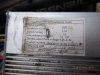
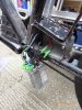
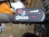
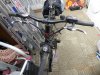
I have been really enjoying my bike since last November. Pre-owned and 2010 manufacture. It suddenly stopped working on a ride and when I got it home I found that the rear wheel motor would run off the ground but with no power worth talking about. If I started it on the ground it would kick and then nothing. I found the thread on the poor battery connection, so I monitored the battery voltage inside the controller box and it remained near 41Volts whether running or not.
So I suppose that I have a problem with the motor or the controller, rather than the battery. Please, any suggestions as to what may be wrong, or perhaps how to diagnose?
I am already missing not getting out!
John Davies.
 

vfr400

Esteemed Pedelecer
Jun 12, 2011
9,822
3,986
Basildon
Can you show a picture of which one you have because there are several versions. Please show any control panel on the handlebars, and if you have the one-into-4 cable that branches in front of the steering head, please show one of the brake or throttle connectors.

There is nothing wrong with your motor. There's nothing in it that can cause it not to run under load when it runs with no load.

If your battery voltage holds firm during the cut-out, it's almost certainly a connection fault. Prime suspect is the motor connectors.

What caused the problem to start? Things rarely happen on their own.
 

JohnD135

Pedelecer
Aug 24, 2020
41
0
Thanks for the reassurance, I was feeling negative. As to what started this, I loaded the bike into the car boot with some difficulty. Could have hit something. I have checked the little connectors around the regulator, etc. Wondered about the cable into the motor, what with it being exposed at the axle. Pictures as requested. Thanks for the help.
 

Attachments

vfr400

Esteemed Pedelecer
Jun 12, 2011
9,822
3,986
Basildon
If everything is original, that must be a Mk2. I don't think I've seen one of those before. The Mk1 had a plastic battery and no control panel, and the Mk3 had an LCD and thin connectors for the throttle and brakes.

Just to clarify, when looking at the control panel, all 4 battery segments are lit when you start. Does anything change at the point the motor cuts out?

One test you could try if you don't see anything obvious on the motor connections: Connect your voltmeter to the red and black wires on the motor hall sensor connector (flat black 5-pin next to thick green, blue and yellow wires). You'll have to peel off the hot melt glue that doesn't do anything useful. It should be around 5v. See what happens to it at the time of cut-out.

I see you have the old white 15 mph speed restriction wires. It's a long time since I've seen them on a controller.

One other thing that might be important. I know the later ones had a motor connector under the frame, just behind the controller. Is there any connector on the motor wire between the controller and the axle?
 
Last edited:

JohnD135

Pedelecer
Aug 24, 2020
41
0
Only connector on the motor wire is half way along the fork, about 10" from the hub.
15 mile speed restriction? So I can go faster? I digress. Hall sensor is a three pin connector. Disconnected it (I am using the throttle) and found 4.7V. Ran motor and it went up to 5.1V.
The 4 battery segments are all on and do not change with motor running or not. Colours of wires to the Hall sensor are YL BLK RD. Voltage between YL BLK.
 

vfr400

Esteemed Pedelecer
Jun 12, 2011
9,822
3,986
Basildon
That connector half-way along the chain-stay is probably not fully in. There's a line that shows how far it has to go. If it doesn't reach the line, you get the problem you described.

The white wires control the speed limit. I can't remember which way round for sure, but I think it's connected foe 15 mph, disconnected for unlimited, otherwise the other way round.

Hall sensor wires are yellow, green, blue (sense wires) and red and black (power wires) - all on the same flat black connector.
 
Last edited:

JohnD135

Pedelecer
Aug 24, 2020
41
0
Unfortunately, it is right in! There are two arrows facing each other to show how far it needs to be in. I thinks it is ok, but could it be a broken wire in that cable, perhaps at the axle? Should I strip the motor to get at the wiring? If that is possible of course.
 

vfr400

Esteemed Pedelecer
Jun 12, 2011
9,822
3,986
Basildon
Unfortunately, it is right in! There are two arrows facing each other to show how far it needs to be in. I thinks it is ok, but could it be a broken wire in that cable, perhaps at the axle? Should I strip the motor to get at the wiring? If that is possible of course.
You have to say whether it reaches the marked line. Pull it apart and make sure you understand where the line is. It runs in the direction of the circumference. The edge of the outer one has to reach it when pushed together.
 

JohnD135

Pedelecer
Aug 24, 2020
41
0
I checked again. Pulled it in and out and it goes right up to the line. I should have said!
 

JohnD135

Pedelecer
Aug 24, 2020
41
0
I pulled the tiny 5 wire connector to the motor and found conductivity between 4 of them, consistent with a semiconductor. That is only one way round. But the 5th one, nothing. This was the red one.
 

vfr400

Esteemed Pedelecer
Jun 12, 2011
9,822
3,986
Basildon
I pulled the tiny 5 wire connector to the motor and found conductivity between 4 of them, consistent with a semiconductor. That is only one way round. But the 5th one, nothing. This was the red one.
I asked you to measure the voltage between red and black during running and cut-out,
 

JohnD135

Pedelecer
Aug 24, 2020
41
0
You wrote, "Hall sensor wires are yellow, green, blue (sense wires) and red and black (power wires) - all on the same flat black connector."

The Hall sensor connector has three wires, yellow black and red. The voltage between the black and red wires is 4.72 Volts. This does not change during running and cut-out
 

vfr400

Esteemed Pedelecer
Jun 12, 2011
9,822
3,986
Basildon
You wrote, "Hall sensor wires are yellow, green, blue (sense wires) and red and black (power wires) - all on the same flat black connector."

The Hall sensor connector has three wires, yellow black and red. The voltage between the black and red wires is 4.72 Volts. This does not change during running and cut-out
The hall sensor connector has 5 wires. I can see it in the photo.
 

JohnD135

Pedelecer
Aug 24, 2020
41
0
Red to black voltage is 4.72V and it does not change with during running or curt-out.
I was looking at the Hall? sensor on the crank rather than in the motor! Sorry.
 

vfr400

Esteemed Pedelecer
Jun 12, 2011
9,822
3,986
Basildon
There are two possibilities that come to mind. Firstly, there's a dodgy connection on one of the phase wires. It could be a connector issue, the cable could be damaged or you've got a dodgy solder joint. Secondly, you could have a dodgy mosfet in your controller. None of those things are easy to test, so you have to do a visual inspection.

Given that it started after some rough loading into your car, the motor cable would be top of my suspects list. The only thing I can suggest is wiggling it close to the axle while it's running with no load to see if anything happens.
 

JohnD135

Pedelecer
Aug 24, 2020
41
0
Thanks for all your help. I tried moving the cable, but could not get things to change. I will start stripping things down to see what I can find. Once again, thanks for your time.
 

vfr400

Esteemed Pedelecer
Jun 12, 2011
9,822
3,986
Basildon
One other thing you can do is to resolder the joints in the controller that carry a lot of current. Maybe one of them has cracked or got compromised somehow. On older controllers, I've seen them melt away, but that would happen fairly soon, not after 10 years.

There are seven joints to check and resolder: the three phase wires, the two battery wires and the two shunt joints. The shunt is a piece of solid wire that looks like a staple and it normally sits at the far end of the controller - the opposite end to the wires.
 

JohnD135

Pedelecer
Aug 24, 2020
41
0
That sounds like an easier job than trying to get the motor apart. I will start with the controller.
 

vfr400

Esteemed Pedelecer
Jun 12, 2011
9,822
3,986
Basildon
That sounds like an easier job than trying to get the motor apart. I will start with the controller.
I forgot that some versions of the Emate have Ananda controllers, which are potted, so you can't get at anything. Hopefully, you don't have one. The Mk1 didn't and the Mk3 did. So, if you see "Ananda" cast into the top of the aluminium box, forget it.
 
Last edited:

JohnD135

Pedelecer
Aug 24, 2020
41
0
It wasn't potted. I stripped it out and re-flowed the solder on the 7 joints, and a few more as well. Having removed the cassette, I looked at the motor and it seems to be sealed! I gather that the motor itself is unlikely to be fried, but a phase wire could be broken? Agitating the cable into the motor has no effect, by the way. Having re assembled, everything is as it was. Low power and if the wheel is stalled, then even less, until the key is switched off and then on. I don't think I went into that detail before.
 

Advertisers