Hall sensors with a 49 in the designation are the wrong type. They're the ones used in throttles to give a variable output. The ones in the motor are bipolar, i.e. on or off. They normally have 42 in the designation, though there are other types. Some controllers require pull-up resistors on the hall output, which hold them on until the magnet switches them off, then it pulls them back up again, otherwise they might stay off. Some halls have the resistor integrated. A pull-up resistor would be around 10k ohms.
I've seen some motors with a small circuit board for the hall sensors, which had the three pull-up resistors and a couple of capacitors. The capacitors are used to take noise of the signal wires. They'd be in the nF range.
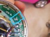
Here's an example that does indeed show 47 ohms. Without studying everything, I can't say why they're that low. There are 4. One is on the 5v supply and the other three are on each output. They're probably for protection or to filter out noise rather than pull-ups.

 151.1 KB Views: 30


