Speed sensor in back wheel of Powabyke Classic

ChrisOfBristol

Pedelecer
Sep 28, 2016
63
2
UK
Mine won't run, so I am testing the components.
1) Motor works.
2) Brake lever motor cutout works (although in the opposite sense to what I would have expected)
3) Throttle works (also in the opposite sense to what I would have expected, but a post on a another thread by VFR400 confirms that this is correct.)
4) On/off switch works.
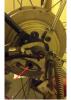
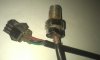
5) Speed sensor in rear wheel hub as shown. The wires are red/black/green. I would expect to put about 5V across red and black and then measure a variation between green and black if I wave a magnet over it. Is that correct? Nothing happens and I can't measure any continuity between any of the wires.
Should the motor run without this? If so I could test everything else without worrying about the sensor.


37690
 

Nealh

Esteemed Pedelecer
Aug 7, 2014
20,125
8,225
60
West Sx RH
You should see continuity for each wire end to end.
If it is suspect just but any 3 wire £10 sensor to use.
 

vfr400

Esteemed Pedelecer
Jun 12, 2011
9,822
3,986
Basildon
You should see continuity for each wire end to end.
If it is suspect just but any 3 wire £10 sensor to use.
I think the Powabyke one is different. It might be a proximity sensor

What's the voltage on the socket in the controller between red and black?
Where is the sensor located and what does it sense?
 
  • Like
Reactions: ChrisOfBristol

ChrisOfBristol

Pedelecer
Sep 28, 2016
63
2
UK
You should see continuity for each wire end to end.
Not checkable unfortunately, as the wheel ends of the wires are concealed inside the metal housing. It should be possible to see that if you look at the image quite closely.
If it is suspect just but any 3 wire £10 sensor to use.
I don't suppose it is a standard fitting, so I assume you mean the chip - I may have a spare chip around somewhere - any idea which pin goes to which colour wire?

If this is a standard sensor, I imagine someone on here will know how to test it. That might be useful for other people too.
 

ChrisOfBristol

Pedelecer
Sep 28, 2016
63
2
UK
I think the Powabyke one is different. It might be a proximity sensor

What's the voltage on the socket in the controller between red and black?
(Note that the test supply is about 28V, it's not from a 36V battery.)
Now measured at 11.8V. This is more than the 5V applied to the sensor in the throttle, so is this a different type?
I have also measured 524 Ohms between Black and Red, 1772 Ohms between Green and Black. Nothing in the opposite direction or between Red and Green. I don't know which multimeter lead is +ve and can't check that until tomorrow.

Where is the sensor located and what does it sense?
It is inserted into the motor hub from the outside so that it scans a rotating disk on its flat surface (like a brake pad facing a brake disk.) The disk looks as though the metal surface varies - so I imagine this sensor is detecting magnets.
 
Last edited:

WheezyRider

Esteemed Pedelecer
Apr 20, 2020
1,672
921
On my ancient Powabyke the speed sensor (which looks like yours) screwed into a "redundant" band brake on the left side of the rear hub. When I disassembled this, I found 4 magnets glued to the inside of the band brake hub. So I assume it's some early kind of Hall sensor.
 
  • Like
Reactions: ChrisOfBristol

ChrisOfBristol

Pedelecer
Sep 28, 2016
63
2
UK
On my ancient Powabyke the speed sensor (which looks like yours) screwed into a "redundant" band brake on the left side of the rear hub. When I disassembled this, I found 4 magnets glued to the inside of the band brake hub.
Dead right Wheezy! Image shows hole that sensor screws into.
37745

I wouldn't say that the brake was "redundant" though, since it's the only back brake. Certainly over complicated and over heavy for very small advantages though.

So I assume it's some early kind of Hall sensor.
I think you are right about this too. It is odd that the supply to it is 12V though. As you say perhaps it is an early version so more complex and requiring a higher voltage. I will test it at 12V.

It would be a great help if a circuit diagram was available for this model. it wouldn't give away any technical secrets because most of the technology choices involved have now been abandoned. Neither would it deprive workshops of business as it wouldn't make economical sense anyway.
 
Last edited:

vfr400

Esteemed Pedelecer
Jun 12, 2011
9,822
3,986
Basildon
They had a device that eliminated that speed sensor and converted to twist and go throttle. It had the name PTDISABLE. It must have been something that used the power from the red and black (probably 5v) and gave a simple pulsed signal.

You could try making one from a 555 timer, like here (first section). I would aim for a frequency of about 800Hz, but if you use a small preset pot, you could have it adjustable in case 800hz doesn't work. Rx C needs to be about 0.001, so a 1k resistor and a 1 microfarad capacitor would give F = .722/ (1000 x .000001) = 722Hz

 
Last edited:

WheezyRider

Esteemed Pedelecer
Apr 20, 2020
1,672
921
Dead right Wheezy! Image shows hole that sensor screws into.
View attachment 37745

I wouldn't say that the brake was "redundant" though, since it's the only back brake. Certainly over complicated and over heavy for very small advantages though.


I think you are right about this too. It is odd that the supply to it is 12V though. As you say perhaps it is an early version so more complex and requiring a higher voltage. I will test it at 12V.

It would be a great help if a circuit diagram was available for this model. it wouldn't give away any technical secrets because most of the technology choices involved have now been abandoned. Neither would it deprive workshops of business as it wouldn't make economical sense anyway.

Ah, ok, on your bike the band brake is connected up. On mine it wasn't, the bike had rim brakes that were connected, but the band brake was just there to house the speed sensor (and add weight!)

After experimenting a bit with my old brushed hub motor, I got fed up and changed it for a modern brushed motor. They are more efficient, more powerful, less noisy and about half the weight. Plus the new hub allowed me to have more than 3 granny gears.
 

ChrisOfBristol

Pedelecer
Sep 28, 2016
63
2
UK
I got fed up and changed it for a modern brushed motor.
Yes, the technology is all outdated. Brushed motor, lead-acid batteries and a heavy and unstylish frame to carry the weight of the batteries. The controller is big and ugly and the throttle and brake cutout work in the wrong sense electrically so would be difficult to replace if needed. I have no idea how to test the speed sensor yet, since no-one on here seems to have either.
I could update some of the technology but there's not a lot of point since it all needs updating. I'm going to get it going and then sell it for whatever I can get. Someone might appreciate it as a very cheap introduction to electric bicycles - as I did when I bought it.
 

WheezyRider

Esteemed Pedelecer
Apr 20, 2020
1,672
921
Yes, the technology is all outdated. Brushed motor, lead-acid batteries and a heavy and unstylish frame to carry the weight of the batteries. The controller is big and ugly and the throttle and brake cutout work in the wrong sense electrically so would be difficult to replace if needed. I have no idea how to test the speed sensor yet, since no-one on here seems to have either.
I could update some of the technology but there's not a lot of point since it all needs updating. I'm going to get it going and then sell it for whatever I can get. Someone might appreciate it as a very cheap introduction to electric bicycles - as I did when I bought it.
I see your point, but it does make a good frame to update because of the large battery carrying capacity and also it is pre 2016, so you can have a throttle.

As the speed sensor is magnetic, can you wave it in front of a magnet and see if it goes from conducting to non conducting?

I've kept all the bits I've stripped off of mine, I could dig it out and the controller and see how it behaves. Unless a wire connection to the sensor has broken, my guess is the problem is in the controller.

BTW, are you still using the original power connectors and leads? If not, bear in mind the neutral wire is the positive DC wire!!! That caught me out.
 

vfr400

Esteemed Pedelecer
Jun 12, 2011
9,822
3,986
Basildon
Yes, the technology is all outdated. Brushed motor, lead-acid batteries and a heavy and unstylish frame to carry the weight of the batteries. The controller is big and ugly and the throttle and brake cutout work in the wrong sense electrically so would be difficult to replace if needed. I have no idea how to test the speed sensor yet, since no-one on here seems to have either.
I could update some of the technology but there's not a lot of point since it all needs updating. I'm going to get it going and then sell it for whatever I can get. Someone might appreciate it as a very cheap introduction to electric bicycles - as I did when I bought it.
By deduction, it's a normal bi-polar hall sensor. You apply 5v to the red and black, then measure between ground and the signal wire to see if it switches between 5v and 0v when a magnet goes past in the right direction. Most likely, it will need a pull-up resistor to test it on its own, so for testing, put a 5k or 10k resistor between the 5v wire and the signal wire. If that doesn't work try using it as a pull-down resistor between ground and the signal wire, in which case it should stay 0v and the magnet will switch it to 5v.
 
  • Like
Reactions: WheezyRider

WheezyRider

Esteemed Pedelecer
Apr 20, 2020
1,672
921
I dug out the old junk. I connected up a 36V lithium pack. I got 11.8V on both red and green wires from the controller to the sensor, relative to the central black wire. The resistance values of the sensor were all in the kOhm range. Hope that helps.
 

vfr400

Esteemed Pedelecer
Jun 12, 2011
9,822
3,986
Basildon
Honeywell SS41 can work up to 24v, so modify my above post from 5v to 12v. A 555 timer can work up to 18v, so you can choose either option. For the very low cost, I'd go for the 555, at least to try it.
 

ChrisOfBristol

Pedelecer
Sep 28, 2016
63
2
UK
...it does make a good frame to update...
Agreed - it had occurred to me that it might be suitable for conversion into a cargo bike.
...neutral wire is the positive DC wire!!!
You were lucky you didn't blow anything up! I didn't make any assumptions, just tested the voltages, so I avoided that.

[responses to the technical comments later]
 

ChrisOfBristol

Pedelecer
Sep 28, 2016
63
2
UK
I got 11.8V on both red and green wires from the controller to the sensor, relative to the central black wire.
I've no reason to suspect that the sensor chip doesn't work as it's not a highly stressed component, but the connections between the chip and the wires inside the metal mounting are a bit vulnerable, because they twist unless you are very careful unscrewing it.

I have been testing all the simpler components first before looking at the board - a lesson I learnt last time it went wrong! On that occasion I did a lot of study of the board and its components, then replaced a couple of the semiconductors on the board without success only to realise that the problem was caused by a loose wire in the power lead from the battery, Duh!

I checked the voltage on the socket and found 11.8V too. I was a bit wary of testing the sensor at 12V in case that was caused by a bad board and it might damage the sensor. I'm now confident to do a test at 12V. I shall also take VFR400's tip and try adding a resistor if it doesn't work without.
my guess is the problem is in the controller.
When I have done the testing above and eliminated the speed sensor I will have confirmed that assumption.
The fact that you found 11.8V is also encouraging because it suggests that at least that part of the board is working. Thanks for getting it out and testing it!
 

ChrisOfBristol

Pedelecer
Sep 28, 2016
63
2
UK
I could dig it out and the controller and see how it behaves...
The throttle wire connections to the plug were broken from previous testing. I have resoldered them, but wasn't entirely sure which went where. I think the red was still attached and I studied the board to work out which of the other two was the negative. I think I have guessed right because the throttle worked when I tested it using that assumption.

Should you have time, I'd appreciate it if you were to compare the photo below with your circuit board. I'd like to check that I have put the throttle and speed sensor plugs into their correct sockets and that the throttle wires are in the plug in the right order. It would also be good to know that the power leads were in the right order. It's a long time since I last worked on this so things could have got mixed up :(elebike board (annotated).png
 
Last edited:

ChrisOfBristol

Pedelecer
Sep 28, 2016
63
2
UK
Throttle is 5v, speed sensor is 12v.
I checked the socket that I assumed was the speed sensor socket and it was 12V so I must have identified the speed sensor and throttle sockets correctly.
 
Last edited: