A Spike in EVs Means a Spike in Insulated Gate Bipolar Transistors (IGBTs)
by Jake Hertz
Although as far as I am aware, they are not yet in general usage in e-bike controllers, it may not be long in coming, so if you are one of those people who is always interested in staying up to date, you might find this interesting to follow:-

 www.allaboutcircuits.com
Best wishes
www.allaboutcircuits.com
Best wishes
Andy
by Jake Hertz
Although as far as I am aware, they are not yet in general usage in e-bike controllers, it may not be long in coming, so if you are one of those people who is always interested in staying up to date, you might find this interesting to follow:-
A Spike in EVs Means a Spike in Insulated Gate Bipolar Transistors (IGBTs) - News
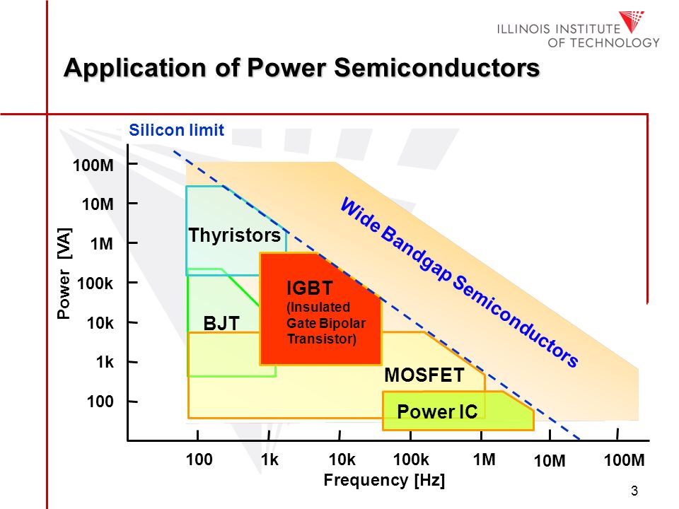
The Insulated Gate Bipolar Transistor (IGBT) has been a key player in the development of electric vehicles. What makes them so valuable?
www.allaboutcircuits.com
Andy