Thumb throttle installation help

Kudoinu

Finding my (electric) wheels
Jul 28, 2018
17
0
36
Hi I wanted to upgrade my bike with an thumb throttle.

The controller on the bike is from Ananda
this one

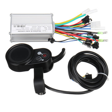
The control panel itself is a simple one with leds only, it does have the push up hills assist to 6km/h which I presume is connected to the wire I need to unplug and replace with a proper grip/thumb throttle. (pictured below) It's the only 3 pin connector in there so I presume it'd be the throttle plug.

RED 5+ Black negative and white the sensor/speed line?


Just checking if anyone could give me some feedback if I'm on the right tracks. I emailed Ananda but let's see what they respond.
 

Kudoinu

Finding my (electric) wheels
Jul 28, 2018
17
0
36
Also investigated a bit more, the 3-pin connector goes to the pedal sensor. I take it it could be then switched to a throttle right?

Any way of connecting both?

Edit: Apparently not? Since the hall sensor reads pulses and not just 1-5 Volts.
 
Last edited:

vfr400

Esteemed Pedelecer
Jun 12, 2011
9,822
3,986
Basildon
No, you can't do that. The pedal sensor sends a pulsed signal. The controller only checks to see if that wire is pulsing in the right pattern. When it sees it, it gives the power set on the control panel.

The walk assist is a simple yes or no switch that the controller monitors. When the switch is on, it sends a fixed 6km/h speed to the motor.

A throttle is a speed controller. It sends out a varying signal in the range 1.8v to 4.2v. The controller uses an analogue to digital converter to change that voltage into a number, then it sends power to the motor to increase the speed until it reaches a speed equivalent to that number.

As well as a connector to attach the throttle, the controller must also have the throttle function programmed into its software. Obviously, the presence of the connector is normally a sign that the function is in the software.

Pull out the controller and disconnect it, then show a picture of it with the wires spread out, so that we can see what you've got and give suitable advice.
 
Last edited:
  • Like
Reactions: Kudoinu

Kudoinu

Finding my (electric) wheels
Jul 28, 2018
17
0
36
No, you can't do that. The pedal sensor sends a pulsed signal. The controller only checks to see if that wire is pulsing in the right pattern. When it sees it, it gives the power set on the control panel.

The walk assist is a simple yes or no switch that the controller monitors. When the switch is on, it sends a fixed 6km/h speed to the motor.

A throttle is a speed controller. It sends out a varying signal in the range 1.8v to 4.2v. The controller uses an analogue to digital converter to change that voltage into a number, then it sends power to the motor to increase the speed until it reaches a speed equivalent to that number.

As well as a connector to attach the throttle, the controller must also have the throttle function programmed into its software. Obviously, the presence of the connector is normally a sign that the function is in the software.

Pull out the controller and disconnect it, then show a picture of it with the wires spread out, so that we can see what you've got and give suitable advice.
I'll do that later today. It doesn't have a connector that is unused so most likely I'd be shopping around for a replacement that has the throttle input plug in that case?
 

Kudoinu

Finding my (electric) wheels
Jul 28, 2018
17
0
36
No, you can't do that. The pedal sensor sends a pulsed signal. The controller only checks to see if that wire is pulsing in the right pattern. When it sees it, it gives the power set on the control panel.

The walk assist is a simple yes or no switch that the controller monitors. When the switch is on, it sends a fixed 6km/h speed to the motor.

A throttle is a speed controller. It sends out a varying signal in the range 1.8v to 4.2v. The controller uses an analogue to digital converter to change that voltage into a number, then it sends power to the motor to increase the speed until it reaches a speed equivalent to that number.

As well as a connector to attach the throttle, the controller must also have the throttle function programmed into its software. Obviously, the presence of the connector is normally a sign that the function is in the software.

Pull out the controller and disconnect it, then show a picture of it with the wires spread out, so that we can see what you've got and give suitable advice.
This probably helps!

But yeah no unused connectors there. So apparently this is cadence sensor only controller? New into swapping controllers and stuff but I guess I'd need to find a compatible one with a thumb throttle?

My rear wheel motor is the Bafang 250W D 10 and the control panel is just a generic yosemite D 15 with leds.

I don't need to go fast but I just need manual throttle adjustment for the winter :)


:Edit:

Also those black and white unused connectors give out 3.6V so probably connectors for lights.
 

Kudoinu

Finding my (electric) wheels
Jul 28, 2018
17
0
36
Also did I get it right. If that controller + dash combo doesn't work.


I could swap this in? Says power 350W on the controller itself but 250W in the listing.

I guess I'd have to make sure it's 250W and not more since It'd burn out my motor I guess? Other than that the dash that comes with that controller fits it of course and the motor is plugged in normally like previously.

I guess I've gotta read into more stuff if there's any gotchas with the compatibility.
 

vfr400

Esteemed Pedelecer
Jun 12, 2011
9,822
3,986
Basildon
The black and white are for brakes. One side is 5v and the other ground, but it's not a real 5v. It's held at 5v by a high value resistor, so you can't take any current from it. The 5v wire is connected to the CPU. When you close the brake switch, it collapses to 0v, i.e, the CPU sees 5v when the brake is off and 0v when the brake is on - a simple digital input. What value you get on your meter depends on its impedence. The meter is taking a small current to measure it, which causes the voltage to reduce.
 
  • Like
Reactions: Kudoinu

Kudoinu

Finding my (electric) wheels
Jul 28, 2018
17
0
36
The black and white are for brakes. One side is 5v and the other ground, but it's not a real 5v. It's held at 5v by a high value resistor, so you can't take any current from it. The 5v wire is connected to the CPU. When you close the brake switch, it collapses to 0v, i.e, the CPU sees 5v when the brake is off and 0v when the brake is on - a simple digital input. What value you get on your meter depends on its impedence. The meter is taking a small current to measure it, which causes the voltage to reduce.
All right, at least I'd have the option to add a button to stop the assist on a slippery surface at the least. (the pedal sensor has a long lag before it stops giving the assist) My older bike had the brake sensors and they were a lifesaver in the winter :)

But yeah to get the throttle I guess I'm looking into a dash + controller combo right?

Also thanks for the help!
 

vfr400

Esteemed Pedelecer
Jun 12, 2011
9,822
3,986
Basildon
Also did I get it right. If that controller + dash combo doesn't work.


I could swap this in? Says power 350W on the controller itself but 250W in the listing.

I guess I'd have to make sure it's 250W and not more since It'd burn out my motor I guess? Other than that the dash that comes with that controller fits it of course and the motor is plugged in normally like previously.

I guess I've gotta read into more stuff if there's any gotchas with the compatibility.
That's an interesting device. I've not see the interface unit before. It could be worth a punt. The only potential problem I can see is where to put it on the handlebars. Make sure that you have the space for it considering the brake lever and gear shifter.
 

Kudoinu

Finding my (electric) wheels
Jul 28, 2018
17
0
36
That's an interesting device. I've not see the interface unit before. It could be worth a punt. The only potential problem I can see is where to put it on the handlebars. Make sure that you have the space for it considering the brake lever and gear shifter.
The placement wont be an issue. Did the watt rating matter though? I guess since if the controller is configured to be 350W and it'd give that to a 250W rated motor it'd work and maybe even be faster but it'd burn out faster right?
 

vfr400

Esteemed Pedelecer
Jun 12, 2011
9,822
3,986
Basildon
Don't take any notice of watts on any controller or motor. It's completely meaningless. That controller has 15 amps written on it, which is what counts. That is probably the same as your present one.
 

jokskot

Pedelecer
Jul 14, 2018
156
47
75
Also did I get it right. If that controller + dash combo doesn't work.


I could swap this in? Says power 350W on the controller itself but 250W in the listing.

I guess I'd have to make sure it's 250W and not more since It'd burn out my motor I guess? Other than that the dash that comes with that controller fits it of course and the motor is plugged in normally like previously.

I guess I've gotta read into more stuff if there's any gotchas with the compatibility.
Slightly cheaper on AliExpress:
 
  • Like
Reactions: Kudoinu

Kudoinu

Finding my (electric) wheels
Jul 28, 2018
17
0
36
Good find!

Only worry I now have is that I need to find some info on how to wire up the hall sensor wires. I read that they might not match and connecting them wrong might smoke my motor and such. Phases will be easy and already checked how to use the intelligent wire to "program" the rotating direction of the motor.

Other wires I don't really have to touch as far as I know.

Does anyone have good info on that?
 

vfr400

Esteemed Pedelecer
Jun 12, 2011
9,822
3,986
Basildon
You won't smoke your motor by connecting the hall sensors wrong. I've never heard of anybody doing that. It is theoretically possible if you're really stupid, which I guess some guys are. Just use small amounts of throttle until the motor runs smoothly. In other words, if the motor is stuttering, buzzing or humming, don't think that holding the throttle wide open is going to solve it. Electrical problems don't work like that.

Every time I've used one of those controllers, it worked first time by connecting all the motor wires colour to colour. The initial problems I had were with setting the parameters because they set the defaults at daft values, like the one for the speed sensor was set to 100 so it showed the speed as 1/100th of the actual and looked like the speed display wasn't working. There was another daft setting for how the throttle worked, which I had to change.
 
  • Like
Reactions: Kudoinu

Nealh

Esteemed Pedelecer
Aug 7, 2014
20,126
8,225
60
West Sx RH
Match the motor halls and phases colour to colour and let the learning sort out the correct sync, we did have a guy recently who wouldn't accept the learning worked because his hub was put in the wrong way round and only worked backwards.
 
  • Like
Reactions: Kudoinu and vfr400

Kudoinu

Finding my (electric) wheels
Jul 28, 2018
17
0
36
You won't smoke your motor by connecting the hall sensors wrong. I've never heard of anybody doing that. It is theoretically possible if you're really stupid, which I guess some guys are. Just use small amounts of throttle until the motor runs smoothly. In other words, if the motor is stuttering, buzzing or humming, don't think that holding the throttle wide open is going to solve it. Electrical problems don't work like that.

Every time I've used one of those controllers, it worked first time by connecting all the motor wires colour to colour. The initial problems I had were with setting the parameters because they set the defaults at daft values, like the one for the speed sensor was set to 100 so it showed the speed as 1/100th of the actual and looked like the speed display wasn't working. There was another daft setting for how the throttle worked, which I had to change.
All right, pulled the trigger on ordering the controller + dash I mentioned above. I'll do some updates over here when it arrives.

Just making double checks so I don't accidentally kill my new fatbike.
Thanks for the help :)
 

Kudoinu

Finding my (electric) wheels
Jul 28, 2018
17
0
36
Finally got my controller, been organizing the cables.

Now though I need to swap some connectors especially on the hall wire ( 6 pins) easy thing to do.

But there's a mystery cable coming from the battery bottom connection.
Which has 3 wires green/ red /yellow


What could this be? https://puu.sh/G2SAG/b981f080e3.png
It connects to the pins that connect to the battery.

And it was connected to the old controller. I'm pretty clear on what the other things were.


This is my old controller unplugged with the mystery wire shown


The new controller looks like this


Kudoinu

Finding my (electric) wheels
Jul 28, 2018
17
0
36
Seems like the diagram was in the bottom of the battery.

It's battery data RX TX etc... do I need to connect those to the new controller?
 

vfr400

Esteemed Pedelecer
Jun 12, 2011
9,822
3,986
Basildon
The new controller won't work with them. The only question is whether the battery will still work without the communication. Do you get the full voltage on the two main battery connections when the battery is switched on? If not, you'll have to change the BMS in the battery.

In 10 years of dealing with every type of ebike, I've never seen comms an that type of battery before, neither have I seen battery comms with an Ananda controller.
 
  • Like
Reactions: Kudoinu

Kudoinu

Finding my (electric) wheels
Jul 28, 2018
17
0
36
The new controller won't work with them. The only question is whether the battery will still work without the communication. Do you get the full voltage on the two main battery connections when the battery is switched on? If not, you'll have to change the BMS in the battery.

In 10 years of dealing with every type of ebike, I've never seen comms an that type of battery before, neither have I seen battery comms with an Ananda controller.
Yes I can read the voltage when the battery is switched on from the key. So I guess I'm just gonna leave that disconnected/unused. :)