Wuxing/Cyclamatic twist throttle has stopped responding - Advice appreciated

Coadey

Finding my (electric) wheels
Apr 20, 2011
9
0
Cambridge, UK
Hi fellow ebikers,

I have a 2009 "Cyclamatic Power Plus" (24V Li-ion) which had been reliable up until yesterday when the throttle control spontaneously stopped responding. The pedal assist still works fine but twisting the throttle simply has no effect.

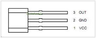
I disassembled the throttle-and-LED switch housing (Wuxing S29X-DX). The metal strip is in place, the hall sensor (S 49E 929) is connected, LEDs work as expected, as does the on-off switch. I also opened up the controller bay under the battery and made sure all the connections there were sound, which they seem to be.

Does anyone have any tips on troubleshooting this further? Is there a common cause for this, could a controller fault be responsible, etc? I'm considering buying a volt meter to check continuity and voltages but don't know what the values should be.

 
Last edited:

vhfman

Pedelecer
Oct 5, 2008
144
0
Hi Coadey

Welcome to the forum.
I am not sure if this will help, but if you get a voltmeter/multimeter, you can do some checks I think the wires should be:-

  • red 5v
  • black 0v
  • white 1v-4v (varies with throttle position)
  • yellow/brown for auxiliary switch
  • green for leds (24v)

The throttle should be the first 3 connections.

Chris
 
D

Deleted member 4366

Guest
As Vhfman say you need a voltmeter. You need to check the votages at the hall sensor end as well as the controller end. Most likely causes are: One of the wires has broken inside the insulation because they're quite thin; Dry joint on the hall sensor; Pin not properly inserted/engaged in the connector at the controller end. Hall sensors are usually quite reliable, although they don't like getting wet. Let us know what you find after testing
 

Coadey

Finding my (electric) wheels
Apr 20, 2011
9
0
Cambridge, UK
Thanks for the tips, I tested the connections to the Hall sensor although the wiring colors are different. There are 4 wires running to the sensor (a red and black wire are soldered together at the middle pin).

Continuity tested good from the the controller box to the sensor and other points, so the wiring and solder connections look good. When powered up, here are the values I get:

Red-to-Green: 4.72 v
Red-to-Red/Black: 4.72 v
Green-to-Red/Black: 0 v

The values don't change at all even when the throttle is twisted. The metal strip on the throttle can hold a paperclip so I know it's magnetized. So would this be a sensor failure?

 
D

Deleted member 4366

Guest
This is strange wiring. Is the switch used to switch off only the throttle or the pedal sensor as well?
Normally the wiring should work like this :
3 wires from the controller to the hall sensor (red 5v, black 0v, and green signal wire back to the controller - voltage changes somewhere between 0 and 5v depending on throttle position)
2 wires to the switch - one is at battery voltage, the other returns the battery voltage to the controller when the switch is on.
2 wires to the LED board - one battery voltage and one at 0v. It's possible to share the 0v from the hall sensor and 24v from the switch.

As you have the 5v and 0v on the hall snesor and the signal wire is not changing, it looks bad for the hall sensor unless your magnet has reversed it's polarity somehow.
 

Coadey

Finding my (electric) wheels
Apr 20, 2011
9
0
Cambridge, UK
Thanks for replying so fast. The switch does cut power to both the throttle and pedal sensor (when "off", there is 0v across all 3 hall sensor pins).

As far as polarity, even waving a refrigerator magnet over the sensor has no effect. I'm surprised the controller isn't seeing this as a "full throttle" signal?

Any idea if I can simulate what the hall sensor would normally send to the controller (e.g. should the green signal wire have 0v when at full throttle)?
 
D

Deleted member 4366

Guest
I believe that the voltage on the green wire should increase as the throttle opens. You could try bridging the signal wire to the 5v to see if it makes the motor run, but make sure the wheel is off the ground. I think I might have a 24v throttle somewhere from when I ordered from BMSbattery and forgot to tick the 36v box. It's a full length one with LEDs, but no switch (I think). Let me know by PM if interested. It won't be expensive.
 

Coadey

Finding my (electric) wheels
Apr 20, 2011
9
0
Cambridge, UK
I tried bridging the red and green at the hall sensor and the motor kicked in for a split second. It wouldn't go any longer than that, but I don't know if that's just part of the logic or a safety mechanism for short circuits.

So at this point it sounds like I should try replacing the hall sensor, and if that fails, the whole throttle. Any idea where to get a replacement sensor (I can't seem to find the specs for the "S 49E 929"). I'll PM to see about that 24V you might have. Thanks again!
 

vhfman

Pedelecer
Oct 5, 2008
144
0
Hi Coadey,
Ok on your measurements.

As far as I can tell the AH-49E Linear Hall-effect Sensor is in a TO92S package.

The pin out for the hall sensor from you picture:
• pin 1 on the left +VCC (should be ≈ +5V)
• pin2 centre Ground (should be 0V)
• pin3 output which should vary between ≈ 1 V to ≈ 4.5V

It looks like it could be the Hall Effect device is the problem.

Depending on how accurate your voltmeter is; it could be the voltage is actually +5V. If this appears at the output signal pin, many controllers will interpret +5V on the signal wire as a short in the throttle or its wiring and shut down.

Chris
 

Coadey

Finding my (electric) wheels
Apr 20, 2011
9
0
Cambridge, UK
Thanks vhfman, that's exactly it! Any idea where I could get a replacement?

Edit: This seems to be the spec sheet for the AH49E:

AH49E pdf, AH49E description, AH49E datasheets, AH49E view ::: ALLDATASHEET :::

I found a couple of potentially similar sensors which accept a wider voltage range:

Hall Effect Sensor - SparkFun - COM-09312 - Proto-PIC.co.uk - UK Suppliers of Electonics - Robotics - SparkFun - LilyPad - Arduino
Hall Effect Sensor - RobotShop

Also this thread pointed me to a few more on rs-online.com:

http://www.pedelecs.co.uk/forum/electric-bicycles/6743-broke-my-throttle.html

The closest matching ones seem to be these two, but can only be had in quantities of 5 or more:

Allegro Microsystems | Semiconductors | Sensors and Transducers | Hall Effect Sensor | Sensor Interfaces |A1302KUA-T
Allegro Microsystems | Semiconductors | Sensors and Transducers | Hall Effect Sensor | Sensor Interfaces |A1301EUA-T

I might try ordering some of those unless anyone has a better suggestion.
 
Last edited:

Coadey

Finding my (electric) wheels
Apr 20, 2011
9
0
Cambridge, UK
To follow up: I ended up ordering a replacement hall sensor from proto-pic.com. After replacing the old one, the sensor delivered a variable 0v - 4.7v depending on throttle position, but it still wouldn't trigger power to the motor (probably because it didn't match the old sensor voltage output closely enough).

I had a replacement 24V throttle sent to me from d8veh (thank you!!) and after installing it the problem was fixed. Thanks everyone for the help, it was a good learning experience.
 
Last edited: