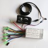
810 and ku65 controller - PAS pedelec question

dgncsk

Pedelecer
Mar 31, 2017
83
6
43
Ankara Turkey
if i change panel voltages, (2 to 1.3 for lo setting lets say) will 810 stock panel and controller work? ( without arduino, since i cant get nice arduino output)

as you remember preset target speeds was way high for my requirements.
 
D

Deleted member 4366

Guest
You need to explain more what you're trying to do.

If all you want to do is change the 810 green wire output voltage, you can (not easy though), but I'm not sure what effect that has. You can test it with a 10k pot. Connect the two ends to ground and any 5v, then connect the wiper to the green wire. You can then test what happens at different voltages. My gut feel is that it works in steps, but that green wire might just work like a secondary throttle input up to 3.8v, then drop down to 4 mph at 4v.

Another way is to use two throttles. take the spring out of one so that it stays in position. Parallel them so that you have an either/or situation and use your Arduino to control a transistor or relay that enables the signal wire on the one without the spring when it detects pedal sensor input. That way you have a continuously variable speed control on the pedal sensor. If you use a relay, don't forget the diode to discharge the back emf.

The 810 green wire output voltages come from simple voltage dividers, so you would need to change the resistors. They're surface mount and tiny, so quite a delicate job.
 

dgncsk

Pedelecer
Mar 31, 2017
83
6
43
Ankara Turkey
thanks for input. i added a diode to drop the voltage slightly. nothing changes. i tried a voltage divider on green line, controller did not work. no throttle! which is weird. then i decided to solder everything back. now again back to arduino.

i will try another hall sensor which is single direction.
 
D

Deleted member 4366

Guest
Using a voltage divider on the green line, you need input from the pedal sensor as well for the controller to give power.
 

dgncsk

Pedelecer
Mar 31, 2017
83
6
43
Ankara Turkey
i did it too. when the voltage is half of 2 volts, it does not respond to anything. including throttle., think it is becasue the first self testing stage fails i guess.

i ordered arduino due to be sure that if pwm filtering works properly or not.
 
Last edited:

dgncsk

Pedelecer
Mar 31, 2017
83
6
43
Ankara Turkey
Update.

Tonight , i did it. There were ground issues. I soldered every sensor panel and throttle related ground wires on arduino. Also i realized that when connected to arduino, panel was loosing some volts... as it acts like feeding arduino on analog pin. 2 volts measured 1.76, 3 volt seemed 2.77 and 4 volt seemed 3.74 so all my preset panel voltages was off. I adjusted them to lower values. I decided to supply voltage over power bank because 5 volt bus was not powerful enough to operate arduino on correctly. It was responding slow. I also realized that my homebrew 10s bms battery has a loose negative wire on socket so i fixed it. Now. I have three pass setting. 2 volts 0 assist. 3 volts approx 40watt assist and 4 volts approx 120 w assist which allows me to barely climb hills here. throttle is always has priority. it gives me approx 250watts max.(its max voltage is 3.9 volts _ controller is between 1.1 to 4.2) on the other hand i ordered another controller and a lcd from aliexpress. In case of emergency...

Thanks for all information you suplied here. Last code works for my controller but may need adjustment. Dont forget to join all sensor panel and throttle ground on arduino gnd pin and feed the hall sensor over arduino too. I will replace hall sensor with single direction one later.
 

dgncsk

Pedelecer
Mar 31, 2017
83
6
43
Ankara Turkey
hello again. my LCD controller i bought after this thread, becasue of hesitation i could not overcome on arduino DAC, unfortunatelly shorted out because of melted motor wires and killing controller together with PAS sensor yesterday night. I returned back to bare minimum setting. now i again i am dealing with 810 led panel and its controller, (managed to reduce the voltage on a similar panel on another bike by adding a diode to lower PAS voltage - 2 to 1.6 etc...). I will do the same and minimum pas will be really minimum level. Here is the problem. I dont remember where to connect green PAS setting wire on this controller. I reads 2 3 or 4 volts when changed over LED panel itself. On aliexpress photos green wire is not connected on LED panel! My memory is playing on me i guess. Any ideas? Please check attached photo. it is very same controller i have.
 

Attachments

Advertisers