Bafang BBS02 Error Code 30

Mike C

Finding my (electric) wheels
Jun 19, 2017
13
0
56
deeside
Fitted my new controller (from eclipse bikes), working perfectly, thanks for everyone's help !
 

jarob10

Esteemed Pedelecer
Jan 22, 2017
270
83
51
Uk
I'm Experiencing a similar problem (bbs01, battery fully charged at 42v) with my spare controller - see picture below

Bearing in mind the system works perfectly with my working controller, could anyone help to establish if my spare controller is permanently fried?

I'm measuring 0v on the +5v line (5v present on the working controller)

I'm also measuring just 2v on the P+ line (42v on the working controller)

I'm measuring 10k ohm for green / blue / yellow wires to battery negative, so I assume MOSFETs are intact?

IMG_2057.JPG
 
Last edited:

Fordulike

Esteemed Pedelecer
Feb 26, 2010
3,802
1,537
I'm Experiencing a similar problem (bbs01, battery fully charged at 42v) with my spare controller - see picture below

Bearing in mind the system works perfectly with my working controller, could anyone help to establish if my spare controller is permanently fried?

I'm measuring 0v on the +5v line (5v present on the working controller)

I'm also measuring just 2v on the P+ line (42v on the working controller)

View attachment 20384
The older Bafangs did have a problem with utilising crappy MOSFETs, so maybe your older controller has these and one or more have blown.

Royal PITA to change out the blown MOSFETs, so most people just change the whole controller.
 

jarob10

Esteemed Pedelecer
Jan 22, 2017
270
83
51
Uk
The older Bafangs did have a problem with utilising crappy MOSFETs, so maybe your older controller has these and one or more have blown.

Royal PITA to change out the blown MOSFETs, so most people just change the whole controller.

Thanks, I'm measuring 10k ohm for green / blue / yellow wires to battery negative, so I assume MOSFETs are intact?
 

Fordulike

Esteemed Pedelecer
Feb 26, 2010
3,802
1,537
Thanks, I'm measuring 10k ohm for green / blue / yellow wires to battery negative, so I assume MOSFETs are intact?
Sorry, I can't help you there, d8veh's yer man for the magic that resides inside motors and controllers ;)
 
D

Deleted member 4366

Guest
The LCD is the switch for controller power. If it doesn't switch on the battery voltage back to the controller, the controller can't do anything and there will be no 5v.

You have to measure the mosfet resistance to each of the positive and negative to get the whole picture. The capacitor can distort the results, so be mindful of that. Maybe short the battery wires before each test to get the same starting point, You're looking for a difference between the three rather than absolute values.
 
  • Informative
Reactions: Fordulike

jarob10

Esteemed Pedelecer
Jan 22, 2017
270
83
51
Uk
The LCD is the switch for controller power. If it doesn't switch on the battery voltage back to the controller, the controller can't do anything and there will be no 5v.

You have to measure the mosfet resistance to each of the positive and negative to get the whole picture. The capacitor can distort the results, so be mindful of that. Maybe short the battery wires before each test to get the same starting point, You're looking for a difference between the three rather than absolute values.
LCD switches on my good controller, but not the spare controller.

I've repeated the y/G/b resistance check after grounding Batt +ve to -ve each time: against the -ve I'm getting 10k ohm on all 3 wires again. Against +ve, each wire slowly rises to open circuit, behaving consistently
 
D

Deleted member 4366

Guest
LCD switches on my good controller, but not the spare controller.
That doesn't make sense. It's a switch. It can't work with one, but not the other.

It receives power from a battery voltage and ground. The wires come from the controller, but are actually just branches off the main battery wires. When you press the power button, the LCD lights up and connects the battery positive wire to one that returns that voltage to the controller to power it. All that works without any influence from the controller. You could smash the controller with a sledge hammer, and that bit would still work.
 
  • Informative
Reactions: Fordulike

jarob10

Esteemed Pedelecer
Jan 22, 2017
270
83
51
Uk
That doesn't make sense. It's a switch. It can't work with one, but not the other.

It receives power from a battery voltage and ground. The wires come from the controller, but are actually just branches off the main battery wires. When you press the power button, the LCD lights up and connects the battery positive wire to one that returns that voltage to the controller to power it. All that works without any influence from the controller. You could smash the controller with a sledge hammer, and that bit would still work.
Understood

As the MOSFETs appear ok, is there a different, repairable controller specific failure that would result in the controller not switching on (and hence no +5v to the display), despite the controller being fed the correct 'switch on' voltage from the display?
 
D

Deleted member 4366

Guest
If I've understood what you've written and I take it at face value, the cable from the controller that doesn't work, which goes from the controller to the LCD, is damaged.
 

AurelV

Just Joined
May 13, 2020
1
0
Sorry to reopen this old thread, but I have an uncommon scenario regarding ERROR 30 and need your help in order to pinpoint the faulty component.
So, I have two Bafang BBSHD kits with the following configuration:
Bike 1: BBSHD / DCP-18 display / Hailong 48V 17.5 Ah battery
Bike 2: BBSHD with Egg rider v2 display / no battery (I use the battery from bike 1)

One day coming back from work on my bike 2 (commuter bike) when using the throttle to get a speedy start the display suddenly turn off. Power back on, the display turns on and used the throttle to accelerate and test the kit and it worked for a few seconds and then the display power off again. Tried second time to power on the display, but no response from throttle or PAS anymore. On the Egg rider app, the error was – Connection Error.
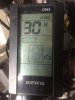
Got home, connected the display from bike 1 and got ERROR 30: Communication Error – my first though was the controller is fried and that was confirmed when trying to connect using the programming cable to connect to the controller and couldn’t succeed.
My new problem is when I connected back the DCP-18 display on bike 1 (the working one) I got Error 30 – Communication Error (same thing with Egg rider display – it shows Communication error). Despite the error, PAS and throttle works, battery voltage is show on both displays.
So, my question is: it’s possible to broke both displays or could be something the battery and BMS because this is the only component which is common to both bikes. Any of you know a way to troubleshoot further?
I don’t have the possibility to get another display or battery for testing ☹.
 

Advertisers