Big Bear - Motor Gone?

stever1957

Pedelecer
Jun 9, 2018
120
41
66
Lake, Isle of Wight
Hello there.

My Big Bear motor started cutting out yesterday.

Thankfully, it started again and got me the couple of miles back home.

This morning, I got a few hundred yards from home and it cut out again. This time, it would not restart and remains inoperative.

I am getting Error Code - 23 on the display.
 

saneagle

Esteemed Pedelecer
Oct 10, 2010
4,194
2,078
Telford
Hello there.

My Big Bear motor started cutting out yesterday.

Thankfully, it started again and got me the couple of miles back home.

This morning, I got a few hundred yards from home and it cut out again. This time, it would not restart and remains inoperative.

I am getting Error Code - 23 on the display.
Motors don't go to become gone. The problem is something other than the motor. Most likely the motor connector isn't pushed in far enough or the wires have melted at the controller end.

Did you take the wheel out or drop the bike just before this started?
 

Nealh

Esteemed Pedelecer
Aug 7, 2014
20,134
8,230
60
West Sx RH
23 is a motor phase fault , a few scenarios are likely.
As mentioned melted bullet connections at the controller or motor cable has cracked/split at the axle exit and two wires are touching.
The latter can happen if the wheel has twisted in the drop outs.

One can check the motor connector is fully pushed in as also mentioned, over time though bullets melting aren't uncommon.
 

Woosh

Trade Member
May 19, 2012
19,529
16,466
Southend on Sea
wooshbikes.co.uk
Error 23 is usually caused by the motor cable connector not fully inserted.
You need to push the motor end of the connector which is about 20cm from the wheel axle until the circle imprinted on it meets the lip of the controller end of the connector.
Let me know if you need a closeup picture.
 
Last edited:

stever1957

Pedelecer
Jun 9, 2018
120
41
66
Lake, Isle of Wight
23 is a motor phase fault , a few scenarios are likely.
As mentioned melted bullet connections at the controller or motor cable has cracked/split at the axle exit and two wires are touching.
The latter can happen if the wheel has twisted in the drop outs.

One can check the motor connector is fully pushed in as also mentioned, over time though bullets melting aren't uncommon.
Well, I couldn't see any obvious problem in any of the areas mentioned.
After I've restarted the display, then applied the throttle, I do hear a very brief click, coming from the motor.
I'm now seeing Error Code - 30 on the display.
 

Woosh

Trade Member
May 19, 2012
19,529
16,466
Southend on Sea
wooshbikes.co.uk
Code 30 is communication error. Unplug the throttle to see if the error goes away.
Please email support@wooshbikes.co.uk - Andy will help you fix it.
 

saneagle

Esteemed Pedelecer
Oct 10, 2010
4,194
2,078
Telford
We're you using the thrott
Well, I couldn't see any obvious problem in any of the areas mentioned.
After I've restarted the display, then applied the throttle, I do hear a very brief click, coming from the motor.
I'm now seeing Error Code - 30 on the display.
The motor connector must be ALL THE WAY IN to the MARKED LINE.

If you check the motor connectors properly and you didn't find anything wrong, check that the motor cable isn't damaged where it comes out of the axle. If that's not it, you can only test further with a multimeter. You need to test the MOSFETs in the controller, which is very easy with the meter.

Whatever you do, do not hold full power while it's like this because that will blow the MOSFETs in the controller, then you have two problems to sort out.
 

saneagle

Esteemed Pedelecer
Oct 10, 2010
4,194
2,078
Telford
I have a multimeter, but wouldn't know a MOSFET from a mole.

How are they accessed; what do I test for?.........and so on.
They're in the controller, which is in the compartment at the front of the battery where you checked for melted wires and that the thin wires in the hall sensor connector from the motor are all in properly and the connector not dirty.

You disconnect the red and black battery wires, then disconnect the thick blue, yellow and green motor wires (the ones that melt or are not gripped tight enough). Set the meter to 200k resistance, then put one probe on the black battery wire and the other on each of the three motor wires to measure the resistance. The three results should be the same as each other and in the range 5K to 25K. Repeat using the red battery wire. Again the three results should be the same as each other and in that same range.
 

saneagle

Esteemed Pedelecer
Oct 10, 2010
4,194
2,078
Telford
By the way, I have the controller from my wife's Woosh Petite bike (she uses an etrike now). Will that be the same controller as the Big Bear?
No need for courage. there's no danger and nothing can go wrong. When your ebike has a problem you use tests and logic to find the cause of the problem, then you know what you have to do. Don't start thinking ahead.

You can find what's wrong with any ebike using a few simple tests that take minutes to do. When you don't know about these things, it seems impossible, but it really is easy. The biggest problems we have in trying to help people on this forum is that they don't listen, they think they know what the problem might be, they keep confusing us with irrelevant facts, they don't tell us pertinent facts and they don't have the confidence or willingness to do simple tests.
 

stever1957

Pedelecer
Jun 9, 2018
120
41
66
Lake, Isle of Wight
No need for courage. there's no danger and nothing can go wrong. When your ebike has a problem you use tests and logic to find the cause of the problem, then you know what you have to do. Don't start thinking ahead.

You can find what's wrong with any ebike using a few simple tests that take minutes to do. When you don't know about these things, it seems impossible, but it really is easy. The biggest problems we have in trying to help people on this forum is that they don't listen, they think they know what the problem might be, they keep confusing us with irrelevant facts, they don't tell us pertinent facts and they don't have the confidence or willingness to do simple tests.
Many thanks.

I've just done the multimeter tests on my wife's old controller. Now I'm off to test mine.
 

stever1957

Pedelecer
Jun 9, 2018
120
41
66
Lake, Isle of Wight
Okay, now I can see some melted things, ie the plastic, protective coverings for the connections between the two yellow wires and between the two blues wires.

Indeed, I had difficulty disconnecting the two blue wires.

Anyway, here are my results:

Red battery wire - yellow wire - Zero
Red battery wire - blue wire - around 3k
Red battery wire - green wire - around 6k

Black battery wire - yellow wire - around 6k
Black battery wire - blue wire - around 3k
Black battery wire - green wire - around 6k
 

saneagle

Esteemed Pedelecer
Oct 10, 2010
4,194
2,078
Telford
Do the test one more time. If it's the same result, you'll need a new controller. Look on the controller's label t see what the maximum current is. I can't remember what the Big Bear has. I seem to remember 20A, though it might be a bit less. Look at the other controller and compare the maximum current. It might be lower, which will work, but you get a bit lkess power. If you want to try the other controller, make sure that each connector has the wires in the correct sequence to match. If the other bike has a different LCD, it still might not work unless you use the matching LCD.. There are ways around that, so do the tests, try any changes and report back the results.

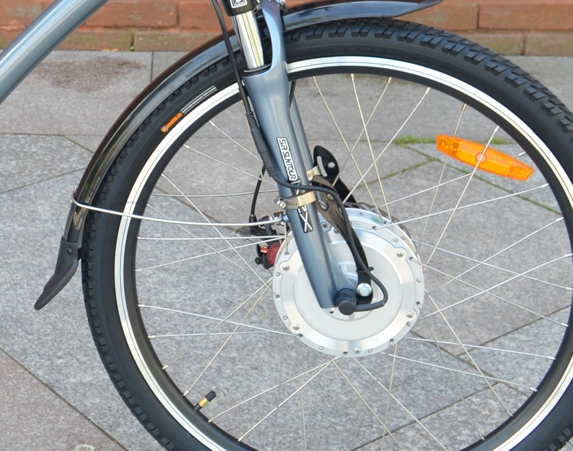
MOSFETs are like electronic switches. The motor is connected directly to the battery, but the MOSFETs are switched off. the controller opens them in high frequency timed pulses to work the motor. When a MOSFET is damaged. it doesn't switch properly and the motor can't work. Your green one looks OK, so is working and tries to turn the motor, which is what causes the click, but the others might be compromised and prevent the motor from turning. It needs all three to work properly. Actually, there are 6 of them - two for each colour, of which one works for a forward pulse and the other a backwards one. you need both forward and backwards pulses on each colour to make the motor go forwards.
 
Last edited:

stever1957

Pedelecer
Jun 9, 2018
120
41
66
Lake, Isle of Wight
By the way, once I'd got everything out of the controller's box, I had a heck of a job getting it all back in again.
Also, there are so many wires to connect, it'll be a daunting task to swap controllers.
 

Advertisers