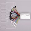
Hi, I have a Chinese Noname 36V, 250W brushless ebike controller which works fine. I have now decided to connect brake levers with switches in order to implement the braking function on the controller. Like many controllers mine has "Brake High" and "Brake Low" connectors. I only recently discovered that 'high' and 'low' refer to the degree of braking, but that is not the problem.
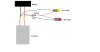
The Brake High has two wires, which I measure as Ground and 5 volts; I had assumed that the 5 volt line was from a pull-up resistor to one of the microcontrollers inputs, and using the brake lever switch to connect this to ground would cause motor power to be cut, but in fact nothing happens! Does this mean the controller is faulty in this function? I'm also puzzled as to how the Brake Low function would be connected, as there is only one wire in the connector, which is neither Gnd or Vcc; no doubt I'm missing something here?
Any advice or suggestions would be most welcome.