Help needed please

KERABO

Pedelecer
May 26, 2022
34
0
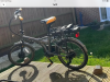
I have bought a cheap folding Ebike. I had assumed the battery would be faulty but it is fully charged and seems ok. All control lights work as they should. It appears to be pedal assist only.
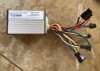
This is 36v front wheel drive.
When I rotate the pedals I can see the pedal sensor light flash.
All the wiring looks intact.
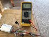
I have a quality multimeter so could anyone guide me as to what and how to test so I can locate what’s faulty please.
a new controller seems quiet expensive so would like to be sure before I spend anything.
Thanks
 

Attachments

sjpt

Esteemed Pedelecer
Jun 8, 2018
3,694
2,677
Winchester
A common and simple problem is if the connection to the motor is not pushed fully home.
It may well be on the cable from the motor about half way up the forks.
It needs to be pushed really firmly; there are often little arrows that need to come completely together.
 

KERABO

Pedelecer
May 26, 2022
34
0
Hello
will everything lights up and I can alter settings but when I pedal there is no power to the drive wheel
Pedal sensor flashes as it’s turned.
Battery showing 36v
the only control on the handlebars lights up and can be adjusted.
all connectors To the ECU and the motor are fully connected.

thank you
 

Nealh

Esteemed Pedelecer
Aug 7, 2014
20,193
8,241
60
West Sx RH

KERABO

Pedelecer
May 26, 2022
34
0
Thanks for the replies
I did try disconnecting the Brake switches but still the same.

the pedal sensor is very close and very firmly fixed. I didn’t know but someone mentioned a LED on the sensor and yes when rotated the correct direction it flashes.

Never heard of Mosfets but I will follow the link.

Thanks for the help.
 

Nealh

Esteemed Pedelecer
Aug 7, 2014
20,193
8,241
60
West Sx RH
If you have a shorted controller mosfet or failed motor Halls then the system won't work.

One expects this is why the bike is non working and was sold.

If you find the fault is the controller then you are best to replace it and the display with a new matching pair to guarantee thier 100% compatibility, one can't simply just buy a new controller on it's own unless it is from the same maker. You will not be able to though be able to buy a Santroll controller as they are OEM only.
 

saneagle

Esteemed Pedelecer
Oct 10, 2010
4,346
2,138
Telford
You've checked all the obvious things, now the only way forward is to get out the meter and start testing. One last thing before that because there might be some misunderstanding. There should be a connector on the motor cable about 10 inches from the axle. It must be pushed in all the way to the MARKED LINE, not just in tight. The line must line up with the edge of the connector, not close to it.
 

KERABO

Pedelecer
May 26, 2022
34
0
I have done the test on the controller as is shows on the link.
I am thinking all are ok?
one strange thing is the resistance test is sensitive to which way the wires are connected and that surprised me.
so I have zero in everything but if I put my test wires reversed it works.
I will refit it and try to test the motor
one pic missing but all the same.
Thank you
 

Attachments

KERABO

Pedelecer
May 26, 2022
34
0
I Tested the 3 wires that go to the wheel from the ECU and all were 5v
I was not able to enter the wires so tested at the open connector from the ECU.
I need to find a way of getting through these very thin wires to get a connection.
I may have to get the wife to help.
the only test I can not do is the one where I rotate the wheel.
The pedal sensor has a feed and earth but can I test the signal or better still can I bypass it so it has to run?
I work on cars and trucks so this is completely new to me but interesting.
Thanks Ken
 

Nealh

Esteemed Pedelecer
Aug 7, 2014
20,193
8,241
60
West Sx RH
Try the Black to phase wire test using the 20 ohm or 200 ohm scale , 0.5 ohm resistance is very low.
One expects usually to see 7 -15 ohms , in my tests 9 -10 ohms has always been typical.
 

KERABO

Pedelecer
May 26, 2022
34
0
I thought I had done that one.
did Red to the phase wires and Black to the phase wires or am I getting confused ?
 

saneagle

Esteemed Pedelecer
Oct 10, 2010
4,346
2,138
Telford
I have done the test on the controller as is shows on the link.
I am thinking all are ok?
one strange thing is the resistance test is sensitive to which way the wires are connected and that surprised me.
so I have zero in everything but if I put my test wires reversed it works.
I will refit it and try to test the motor
one pic missing but all the same.
Thank you
That test is completely wrong. It's not how you do it. You set your meter to 200k scale, then measure the resistance between the battery negative and each motor phase wire to get three results, then repeat using the battery positive. Each group of three should be the same as each other and somewhere roughly in the range 5k to 24k.

To test hall signals, remove the glue that's in the back of the connectors, then you can stuff your probes up there to measure.
 
  • Like
Reactions: KERABO

KERABO

Pedelecer
May 26, 2022
34
0
Ok I try again but going away so won’t be for a few days.
the link said Ohms 200 or the Diode test setting.
all reading were 5k and just above if I read it correctly

thank you for your help
 

KERABO

Pedelecer
May 26, 2022
34
0
I had another go at testing.
It’s difficult but I managed to put some pins into the wires from the ECU to the drive wheel.
Black to Yellow and Black to Green only show .1v each
Black to Blue shows 5v but if I turn the wheel there is no movement .


Thanks Ken
 

saneagle

Esteemed Pedelecer
Oct 10, 2010
4,346
2,138
Telford
I had another go at testing.
It’s difficult but I managed to put some pins into the wires from the ECU to the drive wheel.
Black to Yellow and Black to Green only show .1v each
Black to Blue shows 5v but if I turn the wheel there is no movement .


Thanks Ken
Did you turn the wheel backwards? The results are not very plausible.
 

KERABO

Pedelecer
May 26, 2022
34
0
Did you turn the wheel backwards? The results are not very plausible.
Another try

I got the wife to move it very slowly as I held the test wires.

approx 5v on each wire. When the wheel it turned against the magnets it drops to about 2v roughly and back up.
very tricky to get a connection but pretty sure that’s correct.

Thank you
Ken
 
Last edited:

Nealh

Esteemed Pedelecer
Aug 7, 2014
20,193
8,241
60
West Sx RH
Another try

I got the wife to move it very slowly as I held the test wires.

approx 5v on each wire. When the wheel it turned against the magnets it drops to about 2v roughly and back up.
very tricky to get a connection but pretty sure that’s correct.

Thank you
Ken
The Hall test is satisfactory , no issues with them from your results.
Try the Phase resistance test again on the 20 or 200 ohm setting you need to see about 7 - 15 ohms registered on the ve- and anything barring 0 on the ve+ tests.
 

Advertisers