Help wiring Brompton Tongxin controller

moremeba

Pedelecer
Mar 24, 2015
27
1
58
Hi all, my conversion kit for my Brompton has arrived from China, however there are no wiring instructions for the controller.
Most are obvious and by process of elimination i think i have got them all but one.
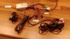
The throttle has a 4 wire plug which i assume is to control the motor and a 2 wire plug(yellow and brown wires) for what i assume is to provide power to the throttle. Its the 2 wire plug that i am stumped with.
The controller has 2 x possible leads that will fit the 2 wire plug. One is red and black, the other is red and brown.
Would anyone know what one i should use?
Please see photograph that my explain the above better.
tongxin.JPG

Many thanks as always

Barry
 

Alan Quay

Esteemed Pedelecer
Dec 4, 2012
2,351
1,076
Devon
Sorry, but pics,are too blurred to make any sense.

My guess is that your throttle has extra functionality.

A normal throttle uses 3 wires: 5v, 0v, and signal.

Perhaps yours also has battery voltage meter, or a switch?
 

moremeba

Pedelecer
Mar 24, 2015
27
1
58
Hi Alan, many thanks for taking the time to reply.
The throttle has a switch so i guess that what the extra 2 x wires are for.
Now i just need to understand what pair of wires from the controller to connect these to.

Regards
 
D

Deleted member 4366

Guest
Yellow and brown are for the switch on the throttle.

The red and brown are probably the ignition switch. To be sure, you'd need to test with a meter. The ignition works by sending battery voltage up the red one, and when joined to the brown, back down the brown to the controller to power it, so you would connect it to the throttle switch, which would then be your on/off switch for the controller.

When you have a LED display, there's normally 4 wires: a red one carries battery voltage to the display; the switch on the display sends it back down another wire (brown?) to power the controller; a signal wire for the pedal assist level (white?); a ground so that the battery voltage can be used to power the display (black).

You don't need an ignition switch if the display already has one, so it's not usual to see both, though I have seen it before. You can test with a multimeter set to beep (continuity). Put your probes on both red wires for the display and in that two-wire connector. If it beeps, they're both battery voltage. Do the same for both browns. If it beeps, they're in parallel, so they are both returns to power the controller, in which case the two-wire connector is redundant. The only absolutely sure way to determine what they do is to open the controller. The power for the controller is connected directly to the big resistor in it, so, whichever (or both) is connected to a track that goes directly to that resistor is the ignition wire.

The red and black 2-wire connector is almost certainly battery voltage, which you can use for lights (from Banggood.com). You can test it with a voltmeter.

The white thing is a programming lead.
 

moremeba

Pedelecer
Mar 24, 2015
27
1
58
Hi d8veh, i well and truly ballsed up the wiring and looks like i have fried the controller.
I connected all up as i thought it should be:-
Yellow motor to yellow controller
Green motor to green controller
Blue motor to blue controller
Red and black to the battery
The display connector to what i thought was correct
The throttle to what i thought was correct.
However i could not get the motor to spin with the throttle or the display control
After a lot of changing around to prove things i think i ended up mistakenly putting the 2 wire red/black connector into the throttle yellow/brown and thats when i heard a noise from the controller and now i cannot even get the display control to light the LEDS. So i assume i have ruined the controller.
Would you know where i can get one or do i need to go back to outrider?
I wanted to prove the motor works before i send it off to be laced into my wheel.

Many thanks
 

oldgroaner

Esteemed Pedelecer
Nov 15, 2015
23,457
32,608
79
I don't see any hall effect wires to the motor, if it is a non hall one surely it wont turn unless you start it spinning,manually, have you tried that?
 

moremeba

Pedelecer
Mar 24, 2015
27
1
58
Hi oldgroaner. I did not try your suggestion of spinning the motor manually to get it spinning. Trouble is i have fried the controller now so cannot even try your suggestion.
From what i can make out the voltage regulator on the board seems fried as i cannot get the any power to the throttle or pedelec dispaly.
I have contacted outrider to see if they will send me a new controller as i cannot seem to find a compatible one elsewhere. Trouble is the lead time from them is approx 2 weeks and i was hoping to send the motor away to get it laced but dont want to do that until i prove it works.

Best Regards
 
D

Deleted member 4366

Guest
Those red and black wires are direct battery connections. They don't go through any of the components in the controller, so no serious damage can be done; however, the connection to those wires will be along tracks on the PCB, which have probably burnt and there may be branches on it to provide the battery voltage to other things, like the LCD. If you can solder, it should be an easy repair to replace the tracks with wires.

It's a sensorless controller, which are not so common today, especially if you want a good one, and there can be compatibility issues with some motors. It might be a good idea to open it up to see the damage first. Take of the two end-plates, the three screws in the side, then slide the contents out.
 

moremeba

Pedelecer
Mar 24, 2015
27
1
58
Thanks again d8veh for the advice.
I took the controller apart. There is no obvious damage to the board but the 78M05 voltage regulator looks burnout.
That was the only obvious damage i could see.
I have order some from RS to see if that cures the problem.

Best Regards
 

Swytch Bike

Trade Member
Sep 10, 2014
154
68
34
Hi oldgroaner. I did not try your suggestion of spinning the motor manually to get it spinning. Trouble is i have fried the controller now so cannot even try your suggestion.
From what i can make out the voltage regulator on the board seems fried as i cannot get the any power to the throttle or pedelec dispaly.
I have contacted outrider to see if they will send me a new controller as i cannot seem to find a compatible one elsewhere. Trouble is the lead time from them is approx 2 weeks and i was hoping to send the motor away to get it laced but dont want to do that until i prove it works.

Best Regards
Let us know if you want to go down the route of a replacement controller in the short term.

Your accessories look different than ours though so you'd probably want to go for our full DIY control kit which lucky for you is on offer right now and not costing much more than just a controller and display:
http://www.pandaebikes.com/product/diy-electric-bicycle-e-bike-kit-display-controller-throttle-pas-brakes/
 

Advertisers