
Having bought the Moli P42's, I have quickly built the battery up ready for use.
Being only 12s2p the battery is just shy of 370wh at 8.4ah, but can easily do more then 40a continuously.
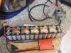
The first job I do is cut the first and last cell buss so I can pre solder ready for the discharge wires to be soldered on.
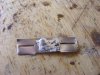
Next is to spread/fan the wire ends out and solder on to the buss.
Doing this now means no heat is applied to the cells causing severe heating up.
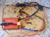
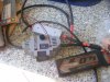
The BMS is a 12s same port model so charge and dsicharge all occur at the XT60 lead. Discharge should have a female connector so the two ports are seperated.
Sitting on the bms is the charge connector, xt60 male to 5.5mm x 2.1mm male to fit my 12s charger using the std 5.5 x 2.1 female connector.
Inline fuse on the discharge for protection.
I measure and cut all my BMS wires and solder them before starting the battery welding,]once I have worked out the BMS position I then decide where any exterior wiring will end up.
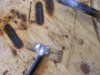
Cells placed in the holders with insulator ring on the + end for a bit more safety.
The interconnector are 0.1mm copper with a cheap nickel coated steel buss on top, the sandwich of the copper gives better current flow. Simply sandwiching the copper between cell steel ends and a slotted bit of H strip on top allows better spot welds then pure copper alone, the H strip gives better penetration thru the copper in to the steel can end. For the likes of the malectric spot welder I am using, the nickel coated steel H strip is purely used for the ability to spot weld the copper easier.
As in the first two pics preparing the discharge wires saves the execessive heating on the battery ends and all one has to do is apply eight welds each end..
My setting is 45 pulses for a good strong weld, previoulsy using pure nickel one had to use 54 pulses to get a good weld, simply using the cheaper steel strip one has less resistance.
I run the malectrics off a turnigy graphene 3s 65c lipo and use a foot pedal for activating the welds manually, once I have the probes positioned.
I have had the malectrics for 3.5 years now and it performs perfectly, for 130 euors it was a good purchase, making ones own battery is no cheaper for a one off then buying one. The difference is though one can use whatever cells he or she wishes so can pick the cell for the application. In my case a lightish weight battery capable of 30 - 40 miles using nice cells, the P42A in this case and the light weight LG HG2 bottle battery in the my last build. I simply don't need to carry 4kg of battery around when instead < 2kg or 1.3kg suffices for my needs.
The senses wires are run of the mill simple small solders on to the corresponding buss 's for which I didn't take pics.
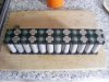
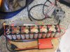
So on this pic I have illustrated the cell sequence. One can't willy nilly solder the wires on they have to correspond with the sequence on the bms connection.
One will find with BMS there are xx positive cell wires and one extra Black B0/B1 wire.
This wire always go to the negative end of the first cell group as indicated by the Blue dot, the positive cells on this side are all the even numbered cells and the opposite side the positive is the odd number cell groups.
The voltage and current has to flow like winding river in Series , so from the 0v marked can the flow is down then up then down and up and so on to the last cell which is the Red series connection.
I mark the cell insulators with a marker pen on the + end 1 - 12 and make sure the corresponding sense wire is matched up.
My cells are at 3.5/3.51v so the voltage I have written corresponds with readings I get.
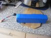
The final battery heat shrunk, under the heat shrink I use 0.4 mm FR4 insulation grp board for a bit of stiif protection for the cells and a bit of capton tape.
I have soldered on an extra 13 wire jst lead to the exterior, should I ever encounter imbalance I don't have to open the pack up.
Total weight come in at 1.98kg.
The pack it self will sit in a padded battery case when I order one from china.
Being only 12s2p the battery is just shy of 370wh at 8.4ah, but can easily do more then 40a continuously.
The first job I do is cut the first and last cell buss so I can pre solder ready for the discharge wires to be soldered on.
Next is to spread/fan the wire ends out and solder on to the buss.
Doing this now means no heat is applied to the cells causing severe heating up.
The BMS is a 12s same port model so charge and dsicharge all occur at the XT60 lead. Discharge should have a female connector so the two ports are seperated.
Sitting on the bms is the charge connector, xt60 male to 5.5mm x 2.1mm male to fit my 12s charger using the std 5.5 x 2.1 female connector.
Inline fuse on the discharge for protection.
I measure and cut all my BMS wires and solder them before starting the battery welding,]once I have worked out the BMS position I then decide where any exterior wiring will end up.
Cells placed in the holders with insulator ring on the + end for a bit more safety.
The interconnector are 0.1mm copper with a cheap nickel coated steel buss on top, the sandwich of the copper gives better current flow. Simply sandwiching the copper between cell steel ends and a slotted bit of H strip on top allows better spot welds then pure copper alone, the H strip gives better penetration thru the copper in to the steel can end. For the likes of the malectric spot welder I am using, the nickel coated steel H strip is purely used for the ability to spot weld the copper easier.
As in the first two pics preparing the discharge wires saves the execessive heating on the battery ends and all one has to do is apply eight welds each end..
My setting is 45 pulses for a good strong weld, previoulsy using pure nickel one had to use 54 pulses to get a good weld, simply using the cheaper steel strip one has less resistance.
I run the malectrics off a turnigy graphene 3s 65c lipo and use a foot pedal for activating the welds manually, once I have the probes positioned.
I have had the malectrics for 3.5 years now and it performs perfectly, for 130 euors it was a good purchase, making ones own battery is no cheaper for a one off then buying one. The difference is though one can use whatever cells he or she wishes so can pick the cell for the application. In my case a lightish weight battery capable of 30 - 40 miles using nice cells, the P42A in this case and the light weight LG HG2 bottle battery in the my last build. I simply don't need to carry 4kg of battery around when instead < 2kg or 1.3kg suffices for my needs.
The senses wires are run of the mill simple small solders on to the corresponding buss 's for which I didn't take pics.
So on this pic I have illustrated the cell sequence. One can't willy nilly solder the wires on they have to correspond with the sequence on the bms connection.
One will find with BMS there are xx positive cell wires and one extra Black B0/B1 wire.
This wire always go to the negative end of the first cell group as indicated by the Blue dot, the positive cells on this side are all the even numbered cells and the opposite side the positive is the odd number cell groups.
The voltage and current has to flow like winding river in Series , so from the 0v marked can the flow is down then up then down and up and so on to the last cell which is the Red series connection.
I mark the cell insulators with a marker pen on the + end 1 - 12 and make sure the corresponding sense wire is matched up.
My cells are at 3.5/3.51v so the voltage I have written corresponds with readings I get.
The final battery heat shrunk, under the heat shrink I use 0.4 mm FR4 insulation grp board for a bit of stiif protection for the cells and a bit of capton tape.
I have soldered on an extra 13 wire jst lead to the exterior, should I ever encounter imbalance I don't have to open the pack up.
Total weight come in at 1.98kg.
The pack it self will sit in a padded battery case when I order one from china.
Last edited:
