Help! Battery to controller connection issues

Doctor Theatre

Finding my (electric) wheels
Aug 29, 2020
7
0
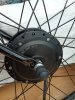
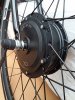
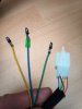
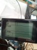
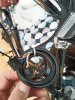
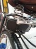
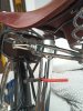
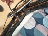
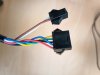
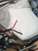
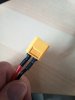
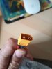
Hi Pedelecs forum - I'm currently converting my bike with an online (Chinese) front wheel conversion kit with rear rack battery combo. It's been going ok but I have hit a stumbling block regarding the battery connection to the control box. I have attached a couple of photos which hopefully explains. I'm also confused about the number/ colour of some of the wires. Some of the wires do not match the combination in the connection blocks but there is nowhere else for them to go. It's very hard/ impossible to find an online manual for my type of control unit and so I cannnot make a direct comparison.
 

Attachments

vfr400

Esteemed Pedelecer
Jun 12, 2011
9,822
3,994
Basildon
Firstly, do not connect anything if you don't know what each wire does. These things are relatively simple when you know about them. We have all the answers here. You only have to ask.

The wiring looks pretty standard to me. Start by connecting just the motor, control panel, battery and throttle. if you need help with that, show us the connectors and wires. Make sure every connector has matching colours side to side. The throttle connector is normally red to red, black to black, third wire to third wire whatever colour the third is.

What sort of control panel do you have?

For the battery, I'd cut off the yellow XT60 connector, solder the wires and insulate with heatshrink because it's cheaper, quicker, easier and more reliable than using a connector. I'm assuming that the wire you show goes to a battery receiver, not the actual battery. If you must have a connector because you're daft or because your battery isn't removable from a receiver, you need an XT60 to match the other one. You can get them as pairs on Ebay.

Note that you have to fit a front motor correctly if you don't want to have to buy a new pair of forks every week. It might be an idea to show us your forks and their drop-outs and a photo of the motor so that we can help you to get it right.
 

Doctor Theatre

Finding my (electric) wheels
Aug 29, 2020
7
0
Firstly, do not connect anything if you don't know what each wire does. These things are relatively simple when you know about them. We have all the answers here. You only have to ask.

The wiring looks pretty standard to me. Start by connecting just the motor, control panel, battery and throttle. if you need help with that, show us the connectors and wires. Make sure every connector has matching colours side to side. The throttle connector is normally red to red, black to black, third wire to third wire whatever colour the third is.

What sort of control panel do you have?

For the battery, I'd cut off the yellow XT60 connector, solder the wires and insulate with heatshrink because it's cheaper, quicker, easier and more reliable than using a connector. I'm assuming that the wire you show goes to a battery receiver, not the actual battery. If you must have a connector because you're daft or because your battery isn't removable from a receiver, you need an XT60 to match the other one. You can get them as pairs on Ebay.

Note that you have to fit a front motor correctly if you don't want to have to buy a new pair of forks every week. It might be an idea to show us your forks and their drop-outs and a photo of the motor so that we can help you to get it right.

Thanks for your rapid reply! Ok, I'll start with the basic connections a you suggested. I've attached more pictures of; the hub motor with it's wires, the control panel, the control panel wires, the red and black power wires from the battery receiver (the battery is removable), the pedal sensor wire (black), and three cables which are the two brakes levers and the twist throttle. Good advise about the battery connection.
Regards, Sam
 

Attachments

Doctor Theatre

Finding my (electric) wheels
Aug 29, 2020
7
0
Great. You have been amazingly helpful and thanks for the link to the LCD - needless to say it didn't come with the manual!
 

Doctor Theatre

Finding my (electric) wheels
Aug 29, 2020
7
0
OK, all looks good. Flat steel forks are perfect. Solder the battery wires. Connect just the throttle, control panel, battery and motor first for testing, then add the PAS and brakes.

Did you get the manual for the LCD? If not, it's here:
Hi there,
So I'm getting closer with the conversion! I've got power but I've got a couple of errors coming up on the SW900 screen. When I apply the right hand brake I get Error 06 which according to the manual is a real-time cruising and when I apply the left hand brake I get Error 02 which is brakes. I have attached a couple of pictures of the wiring options. The first is the SW900 set (multicoloured) with the brown and white wired offshoot for the 'Menu-Up-And-Down-Switch' (there seems to be only one connector option for this which is a single blue wire. The second picture is the two brake lines (both red and black) The options I have for connection is as seen (two black and yellow, one red and black or one single blue) I have tried both black and yellows (Error 02 Brakes) and switched over the black and yellow and red and black but that reverses the Error 06 and Error 02 when I apply the brakes. Any ideas which I should go for?
Many thanks
 

Attachments

vfr400

Esteemed Pedelecer
Jun 12, 2011
9,822
3,994
Basildon
Please keep your questions and info short and clear. I can't understand any of what you wrote, but the pictures show wrong connections.

The brake connectors are black and yellow. You've incorrectly connected one brake to black and red, which is probably a battery voltage supply for lights, so when you operate the brake, it makes a dead short.

Never connect anything unless you're absolutely sure what the wires are for because you can wipe out everything if you connect a wire incorrectly.

The blue wire connects to the other blue wire to make a loop to enable a feature of the controller. That feature could be cruise control (do not enable), electronic assisted braking, self-learning of the motor configuration or anything else. If your motor is working correctly, do not connect them unless you understand what feature it is and how it works.
 
Last edited:

Doctor Theatre

Finding my (electric) wheels
Aug 29, 2020
7
0
Please keep your questions and info short and clear. I can't understand any of what you wrote, but the pictures show wrong connections.

The brake connectors are black and yellow. You've incorrectly connected one brake to black and red, which is probably a battery voltage supply for lights, so when you operate the brake, it makes a dead short.

Never connect anything unless you're absolutely sure what the wires are for because you can wipe out everything if you connect a wire incorrectly.

The blue wire connects to the other blue wire to make a loop to enable a feature of the controller. That feature could be cruise control (do not enable), electronic assisted braking, self-learning of the motor configuration or anything else. If your motor is working correctly, do not connect them unless you understand what feature it is and how it works.
Thanks for your reply. Apologies for the long-winded explanation but it is complicated as I've got so many mismatched coloured wires. I shall leave the single blues for the time being. I don't understand what you mean about the brakes connectors - there are two sets of black and yellow connectors coming out of the controller but the wires from the actual brakes are black and red. If I can't connect them to the black and yellow connectors what can I connect them to? I'm sorry if this is too much info but I don't know how else to describe it. The hub motor, brakes PAS and LCD screen all came in the same kit with the silver controller so unless the suppliers have mixed up the parts this is the only option I have. Attached is a picture of my SW900 with settings switch and corresponding wires (the connector with the brown and white wires has no corresponding connector of those colours from the silver controller unit). If I connect everything as I did before, missing out the single blue wires (which do connect to each other to form a loop), and connecting the black and red brake cables to the black and yellow connectors I ma still left with nothing to connect the brown and white SW900 wire to except a black and red cable from the controller. And they don't connect as they are both male or female (anyway both the same!!)
 

Attachments

Doctor Theatre

Finding my (electric) wheels
Aug 29, 2020
7
0
So I've just taken it out. Worked fine but no change in ODO and speed stayed at 00.0 on the LCD screen. But it goes and the PAS works and the twist throttle works. I'm nearly there!
 

vfr400

Esteemed Pedelecer
Jun 12, 2011
9,822
3,994
Basildon
That's a big wall of text to say, "What do I do with the brown and white wires?"

Brown and white are for lights. Best not to use them because if you overload the transistor, it can damage the LCD.

Set P07=1 for speed display.
 

Doctor Theatre

Finding my (electric) wheels
Aug 29, 2020
7
0
That's a big wall of text to say, "What do I do with the brown and white wires?"

Brown and white are for lights. Best not to use them because if you overload the transistor, it can damage the LCD.

Set P07=1 for speed display.
It really is isn't it!! Yes, I've left the brown and white free. Everything seems ok. I'll play around with my LCD and the menu settings button. Many, many thanks for your help and advice.
 

Advertisers