
My battery give me on B+ and B- 37v , after bms give me 33v , i don’t know what i can check to resolve the problem
Attachments
-
 998.1 KB Views: 14
B- to B+ gives the cell-pack voltage, which is quite low at 37v, assuming you charged it. The only way to check the cell-pack is to check the voltage of the individual cells either on the multi-pin connector or the positions where the pins are soldered to the pcb.My battery give me on B+ and B- 37v , after bms give me 33v , i don’t know what i can check to resolve the problem
I measured the cells individually, all cells give me 3.7vB- to B+ gives the cell-pack voltage, which is quite low at 37v, assuming you charged it. The only way to check the cell-pack is to check the voltage of the individual cells either on the multi-pin connector or the positions where the pins are soldered to the pcb.
The 33v might not be real. It's common to get leakage through the MOSFETS. Typically, you can measure 18v, but I have seen it as high as 33v. If it's leakage, what you measure depends on the impedence of your meter. You can test whether it's leakage by putting a small load on it, like a resistor. The charge leakage is so small that it won't provide any current, so the voltage will collapse to zero as soon as you put a load on it.
If it is indeed leakage that you're measuring, the BMS is switched off for whatever reason. Hopefully the cell voltages will give you a clue.
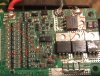
Try this: Look at thr three MOSFETS at bottom right of the photo. The right side pin is connected to B- via the 4 shunts, so should have 37v on them. The middle pin is the output to P-. It's connected to the back-plate, which then goes to the other side of the pcb and back again. It should have 37v when switched on. The left pin is the one that switches the MOSFET on, when it has around 12v to 14v on it. Check that voltage. If it has the 12v, the MOSFETs are faulty. If it doesn't, logic is keeping the BMS switched off.I measured the cells individually, all cells give me 3.7v
10 cells have 3.7vDid you find 10 cells with 3.7v, or did you only find 9 of them?
Wrong way round. You put the black probe on B- (ground), then use the red probe to meausure the voltage on the pins.My friend
I measured the three MOSFETS by multimeter i put red probe on B+ and black probe on MOSFET right pin 37v , middle pin 33.3v and left pin 36.4v and the fourth MOSFET right pin 33v middle pin 33.3v and left pin 19.5v .
Thanks youWrong way round. You put the black probe on B- (ground), then use the red probe to meausure the voltage on the pins.
