Can I alter the board?

Shakes

Finding my (electric) wheels
Jun 17, 2021
17
2
Dear All,

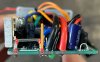
Upon my not-so-recent purchase of a City Blitz CB020 with a 350W motor @36v, I was wondering if I would be able to alter my board in any way to push more power to the motor?

I appreciate I will be limiting my battery life and limiting the lifespan of the motor if I am able to overclock the wattage.

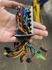
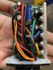
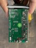
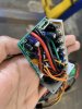
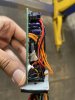
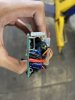
Please find attached photos of my board.

Thank you in advance.
 

Attachments

vfr400

Esteemed Pedelecer
Jun 12, 2011
9,822
3,985
Basildon
The easiest way is to add solder to the shunt. The controller limits the current to a set value, which depends on the length of unsoldered shunt. If you add solder to it, the current increases in proportion to the length you solder, so if you solder 20% of the length, the power goes up by 20%.

From practical experience, 20% is unlikely to give any problems. 30% is the absolute max you should go.

Obviously, the more current that goes through the controller, the hotter it gets, which is why you can't go any higher than 30%.

Current is also restricted by the way the motor works. At low speed, it will get and use all the current the controller allows, but at high speed, the back emf limits the current eventually to zero at its max speed. That means that you can't get a higher max speed by increasing current, but you get more power for hill-climbing and acceleration.

No harm will come to the motor by increasing the current as long as you don't go over 30%. I recommend 20% as a sensible improvement, and maybe 25% if that's still not enough.

The battery can only supply a certain amount of current. It will cut off if you exceed what it's management board allows, or you could blow a fuse. If it's a crappy battery, that can't keep up with the demand for current, the voltage will sag and the battery will be quite stressed, which shortens its life. That's another reason to stick to 20%. Without knowing your battery characteristics, it's not possible to comment further.

To solder the shunt, just put some thick solder around te leg and work your way up until you have the right amount.
 
  • Like
Reactions: Shakes

Shakes

Finding my (electric) wheels
Jun 17, 2021
17
2
Thank you for your reply - Can you please show me where the shunt is and which side to solder on to?
 

vfr400

Esteemed Pedelecer
Jun 12, 2011
9,822
3,985
Basildon
It's that staple-shaped metal wire thing at the end of the board grinning at you in the last photo.
 

Shakes

Finding my (electric) wheels
Jun 17, 2021
17
2
So I'm assuming the solder mount starts from point D going upwards at length 20-30% of distance between B-C or A-D.
I shall await your reply.
 

Attachments

vfr400

Esteemed Pedelecer
Jun 12, 2011
9,822
3,985
Basildon
So I'm assuming the solder mount starts from point D going upwards at length 20-30% of distance between B-C or A-D.
I shall await your reply.
Start by going from the bottom of either leg to no more than half-way round the first bend, so that will be A to B or D to C.
 

Advertisers