carrera vulcan e bike controller replacement problem

steffg60

Finding my (electric) wheels
Apr 24, 2019
11
1
Hi Guys,

New to the e bike game and recently bought a Carrera Vulcan E bike which after 10 miles was cutting out. From research there is no real fix to decided to change the controller and add a throttle last night.

I've come across a couple of problems.
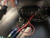
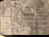
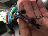
1. I had to swap around the green and yellow motor phase cables as I think the motor was spinning backwards as it was making a nosie but not turning the wheel. Since swapping the cables around the wheel now spins the correct way but is ok?

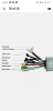
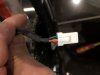
2. I have a connector coming from the pedals with 4 cables. Where I assume is goes on my new controller there is only 3 cables . Which colours go where. The last picture is the pedals connector . The motor is not starting when I start pedalling so something defiantly needs connecting
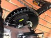
Pedals.jpgNew Controller wiring.jpgconnector on controller.jpgPedal connector.jpg
 

Nealh

Esteemed Pedelecer
Aug 7, 2014
19,990
8,172
60
West Sx RH
You will have to ditch that 4 wire sensor, it might even be a torque sensor . In it's place you will need to fit a standard 3 wire PAS/cadence sensor and magnet ring, to the Red/Black/ Blue 3 pin sm3 connector.
https://www.ebay.co.uk/itm/Electric-Bike-JST-SM-3-Pin-PAS-12-Magnet-Pedal-Assist-Cadence-Speed-Sensor-Ebike/123739610032?epid=813781908&hash=item1ccf749bb0:g:o0kAAOSw~dVcuGFN

You didn't need to swap the phase wiring as the single Green wire is the phase auto learn wire, connecting it together until the controller learns the correct rotation direction then once acheived you disconnect it.

With the auto learn wire you are better to change the phase back to colour to colour and use the auto learn wire. Swapping phases used be for controllers without auto learn mode.
 
Last edited:

steffg60

Finding my (electric) wheels
Apr 24, 2019
11
1
You will have to ditch that 4 wire sensor, it might even be a torque sensor . In it's place you will need to fit a standard 3 wire PAS/cadence sensor and magnet ring, to the Red/Black/ Blue 3 pin sm3 connector.
https://www.ebay.co.uk/itm/Electric-Bike-JST-SM-3-Pin-PAS-12-Magnet-Pedal-Assist-Cadence-Speed-Sensor-Ebike/123739610032?epid=813781908&hash=item1ccf749bb0:g:o0kAAOSw~dVcuGFN

You didn't need to swap the phase wiring as the single Green wire is the phase auto learn wire, connecting it together until the controller learns the correct rotation direction then once acheived you disconnect it.

With the auto learn wire you are better to change the phase back to colour to colour and use the auto learn wire. Swapping phases used be for controllers without auto learn mode.

How do I get it to auto learn? I tried running it a few times but was worried it was burning the motor out. Do you mean the thick green wire labelled motor phase line A on the wiring?
 

steffg60

Finding my (electric) wheels
Apr 24, 2019
11
1
Is it safe to ride the bike just using the throttle obviously Ill have to pedal a little harder on start before increasing the throttle?

I have ordered the new PAS/cadence sensor but it wont arrive until next week.
 

anon4

Esteemed Pedelecer
May 9, 2017
574
90
32
GB
Hi have 3 spare cables on the battery connector what are these for ?
I have experience from modding my own. As said above you need a standard magnet Pas sensor. Plug the phases in colour to colour, then plug the two thin green wires together and turn the bike on. The wheel should start to spin. Disconnect the green loop before turning it off and you're done. As for cutouts, I did experience one or two after changing the controller, but not nearly as bad as before, I think it's the battery BMS chip malfunctioning. It's rare enough to not be an issue with a generic controller I've found. The thin wires have no use on your controller, they are some sort of battery monitoring probably how the suntour display estimates charge %. Hope this helped
 

steffg60

Finding my (electric) wheels
Apr 24, 2019
11
1
Many thanks finished soldering tonight just waiting for the new PAS sensor to arrive Monday
 

Nealh

Esteemed Pedelecer
Aug 7, 2014
19,990
8,172
60
West Sx RH
How do I get it to auto learn? I tried running it a few times but was worried it was burning the motor out. Do you mean the thick green wire labelled motor phase line A on the wiring?
Just got in, in you middle pic the learning wires are the pair of thin Green ones with the M/F black connectors.
Disconnect the thicker phase wires you changed and connect as they were originally, then join the learn wires together turn battery on and give power very gently gently ( be careful using the throttle until all is running nicely, once the wheel rotates correctly disconnect learn wires and switch off. Controller should have learnt the correct direction, you may have to switch on and off a few times and give gentle power if it doesn't learn first time round.

If the motor isn't running correctly don't give full throttle power as you may well damage controller components.
 

Nealh

Esteemed Pedelecer
Aug 7, 2014
19,990
8,172
60
West Sx RH
Is it safe to ride the bike just using the throttle obviously Ill have to pedal a little harder on start before increasing the throttle?

I have ordered the new PAS/cadence sensor but it wont arrive until next week.
You should be Ok with throttle if motor is happily running, if it runs rough or is hesitant don't give it full power (better still don't use the throttle).

When the PAS arrives you need to connect the wiring in the correct sequence Red/Red, Yellow/Black & other coloures together. Some send the connector loose so you can insert the wiring in correct order, if the connector is already wired it may niot be in the correct order so you have to carefully remove pins (using a needle or fine pin to suprress the holding barb) and then re -insert.
 

vfr400

Esteemed Pedelecer
Jun 12, 2011
9,822
3,985
Basildon
It doesn’t matter how you connect the motor wires. The controller will always sort itself out whatever sequence you have. Once you have the motor working in the right direction, leave the self-learning wires disconnected.
 

steffg60

Finding my (electric) wheels
Apr 24, 2019
11
1
Ok it seems my learning wire was disconnected when I started hence why I probably needed to cross wire. You m going to wait until Monday for the pas sensor to arrive and pickup the work again . I’ll definitely document what I’ve done as this a a great bike for the money with the right mods
 

Nealh

Esteemed Pedelecer
Aug 7, 2014
19,990
8,172
60
West Sx RH
will I need to remove the pedals to fit the new PAS senor?
In all cases usually yes chain rings as well, sensor ring is held in place by being pinched tight by the bottom bracket retaining nut or baring case ( just depends on the bb used ). If you have a square taper bb you may have to replace it with one that has a longer shaft. Although it looks neater and out of the way on the drive side it can get knocked or damaged if the chain comes off on the inside, there is no reason why if you wish to is fit it on the non drive side just means getting the orientation correct so it doesn't work when you pedal backwards.
 
Last edited:

Chayman654

Just Joined
Sep 29, 2020
3
0
Can someone help ive got to the motor but my controller has 3 wires the motor has about 10 what do I do?
 

vfr400

Esteemed Pedelecer
Jun 12, 2011
9,822
3,985
Basildon
I hadn't seen the explanation of the torque sensor and its wires before that are in the picture in a post above. The torque sensor output is in the same range as a throttle. It would be interesting to connect the red, yellow and black to the throttle connector of a normal controller to see how it works.

A guy figured out that you can make a max speed only throttle by putting a switch between the yellow and red wires with the original controller and torque sensor. I would say that you could splice in a throttle to the red, black and yellow wires and it would work because IIRC his push button throttle worked independently from pedalling. The green wire tells the controller that the pedals are turning by providing a pulse signal. Somebody should test this because it's an easy modification.
 

vfr400

Esteemed Pedelecer
Jun 12, 2011
9,822
3,985
Basildon
That's a good controller as long as you have the essential LCD to go with it.

You need to cut the connector off your motor cable, then solder all the thin wires to the wires in the white block connector, which should match colour to colour. You should leave the three thick wires unsoldered at first. Strip a few mm of insulation off and fold the bare wire back against itself. That way you can stuff them into the controller's connectors and get a connection. You will have to experiment with the connection sequence because they almost certainly won't go colour to colour. Test with low throttle opening to see what the motor does. If it clicks, judders, jumps or goes backwards, you have to try a different sequence. There are only three sequence combinations, so it shouldn't take long to get the right one. Once you have the correct sequence, you can make a more permanent connection.

The next point is that you have a key-lock connector. You will probably have to bridge those wires to get the LCD to switch on.

When you have the motor wires ready, connect just the battery, the LCD and the throttle. Make sure the throttle wires match red to red, black to black and blue to colour. Test to see if the LCD switches on. If it doesn't, you'll need to bridge the red and orange wires in the key-lock connector. Once the LCD is on, select any level but zero and try the throttle (small amount) to see what the motor does.
 

Advertisers