Chinese Hall sensor problem

B2stealth

Finding my (electric) wheels
Oct 15, 2015
23
0
57
Worcestershire
Well it didn't go too well.
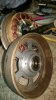
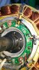
I managed to get down to the nitty gritty of the motor but when I got there I came to the conclusion that my fingers were to big and my eyes too old to try to replace the hall sensor.
So I put it back together after giving it abit of a clean and grease.
Well it's still broke, but no worse for taking it apart.
So now I decided to get a new hall sensor (or 3 ) and fit um.
Well that's easier said than done as I can't get exactly the same numbers sensor.
So really my questions are please...
My hall sensor is 41F 402, I can get 41F but they don't have 402..... but 518, what is the difference in the 3 digits ?
Does anyone do a hall sensor check/replace service or ideally to refurbish or replace what appears to be a copy of a XOFO motor ?
Thanking you in fingers crossed hope
Mark
 

Attachments

Steve Dyson

Pedelecer
Oct 13, 2018
72
13
these were the hall sensors i bought and was questioning whether i bought the right ones as the readings were strange until i plugged in my new controller... they are pretty easy to solder back up and to fit although i had to get a small flat head screw driver and make sure all the gunk was out of the slots for them.... i then used some 2 part epoxy (quick set 10 mins) and filed down the excess... this worked fine for me but beware that when testing them not connected to a controller they show strange values... this is because a 10k resistor is needed between 5v and sense wire to pull the voltage up as the controller does this for you normally.... here is my thread for the things i have been doing to get mine up and running again
http://www.pedelecs.co.uk/forum/threads/judders-and-stops-when-throttle-pulled-on.32852/#post-464438

https://www.ebay.co.uk/itm/6x-Bipolar-Hall-Effect-Sensor-41F-SS41-SH41-SS41F-Electric-Bike-Motor-Repair/281804272538?ssPageName=STRK:MEBIDX:IT&_trksid=p2057872.m2749.l2649
 

B2stealth

Finding my (electric) wheels
Oct 15, 2015
23
0
57
Worcestershire
these were the hall sensors i bought and was questioning whether i bought the right ones as the readings were strange until i plugged in my new controller... they are pretty easy to solder back up and to fit although i had to get a small flat head screw driver and make sure all the gunk was out of the slots for them.... i then used some 2 part epoxy (quick set 10 mins) and filed down the excess... this worked fine for me but beware that when testing them not connected to a controller they show strange values... this is because a 10k resistor is needed between 5v and sense wire to pull the voltage up as the controller does this for you normally.... here is my thread for the things i have been doing to get mine up and running again
http://www.pedelecs.co.uk/forum/threads/judders-and-stops-when-throttle-pulled-on.32852/#post-464438

https://www.ebay.co.uk/itm/6x-Bipolar-Hall-Effect-Sensor-41F-SS41-SH41-SS41F-Electric-Bike-Motor-Repair/281804272538?ssPageName=STRK:MEBIDX:IT&_trksid=p2057872.m2749.l2649
Thanks for that.
I've just ordered some and now building up to take it apart again and have a go.
I did try continuity testing from plug to sensors bit it gave me unexpected results so gave up on that idea.
I hope it's a sensor and not a controller, it wouldn't be so bad if I could just buy of the shelf like for like, I guess that's my fault for buying this bike with my heart and not my head.
Live and learn they say....mmmmm.
So you back on the road now ? Sounds like a pain in the backside.
 

Woosh

Trade Member
May 19, 2012
19,473
16,419
Southend on Sea
wooshbikes.co.uk
testing and replacing a Hall sensor is not a difficult job but you do need some tools to make the job easier.

Testing:
I use a breakout cable at the 9-pin connector but you can do the test at the controller's end. The Hall sensors are usually grouped in a 5-pin connectors, they are 5 thin wires in the same cable with the 3 thick phase wires, ground (black), 5V (red), green, blue and yellow for the signals. Switch on the electrics and measure the voltage between the ground pin and the signal pin. So back and yellow, black and green, black and blue.
On direct drive motors like yours, you can turn the wheel forward or backward, on geared motors, turn the wheel backward to engage the motor. You should see the voltage changing from 0V to about 3.2V as the magnets pass in front of the sensor. Any Hall sensor that is stuck at the same reading when you engage the motor needs replacing.

Replacing:
You need a bit of 2mm heat shrink sleeve and desoldering tool. I use a temperature controlled desoldering station but a pump would do.
check for continuity first. After you open the motor's cover, set the multitester to beep on continuity test, locate the faulty sensor. The sensors are installed with the wide back side to the core, the signal out pin is to the right. After you locate the faulty sensor, cut its legs off and push it out with a flat blade.
Note: keep the nylon spacer that separates the 3 legs, you'll need it later.
You need a desoldering kit to remove the legs without damaging the PCB. Clean the plated through holes carefully before installing the new sensor.
Install the sensor in the cutout slot then place the spacer and sleeves on the new sensor's legs before soldering.

Re test:
Switch the controller back on and confirm that the signal reacts correctly to the movement of the magnets before closing the motor's cover.
 
  • Like
Reactions: Scorpio

Steve Dyson

Pedelecer
Oct 13, 2018
72
13
Thanks for that.
I've just ordered some and now building up to take it apart again and have a go.
I did try continuity testing from plug to sensors bit it gave me unexpected results so gave up on that idea.
I hope it's a sensor and not a controller, it wouldn't be so bad if I could just buy of the shelf like for like, I guess that's my fault for buying this bike with my heart and not my head.
Live and learn they say....mmmmm.
So you back on the road now ? Sounds like a pain in the backside.

my new controller is the same, i couldnt get an exact match but figuring out the wiring is a challenge... at the moment i am happy to just have power to the motor and throttle...

i will be back on the road this afternoon once i have soldered the new linear sensor into my throttle....
 

B2stealth

Finding my (electric) wheels
Oct 15, 2015
23
0
57
Worcestershire
testing and replacing a Hall sensor is not a difficult job but you do need some tools to make the job easier.

Testing:
I use a breakout cable at the 9-pin connector but you can do the test at the controller's end. The Hall sensors are usually grouped in a 5-pin connectors, they are 5 thin wires in the same cable with the 3 thick phase wires, ground (black), 5V (red), green, blue and yellow for the signals. Switch on the electrics and measure the voltage between the ground pin and the signal pin. So back and yellow, black and green, black and blue.
On direct drive motors like yours, you can turn the wheel forward or backward, on geared motors, turn the wheel backward to engage the motor. You should see the voltage changing from 0V to about 3.2V as the magnets pass in front of the sensor. Any Hall sensor that is stuck at the same reading when you engage the motor needs replacing.

Replacing:
You need a bit of 2mm heat shrink sleeve and desoldering tool. I use a temperature controlled desoldering station but a pump would do.
check for continuity first. After you open the motor's cover, set the multitester to beep on continuity test, locate the faulty sensor. The sensors are installed with the wide back side to the core, the signal out pin is to the right. After you locate the faulty sensor, cut its legs off and push it out with a flat blade.
Note: keep the nylon spacer that separates the 3 legs, you'll need it later.
You need a desoldering kit to remove the legs without damaging the PCB. Clean the plated through holes carefully before installing the new sensor.
Install the sensor in the cutout slot then place the spacer and sleeves on the new sensor's legs before soldering.

Re test:
Switch the controller back on and confirm that the signal reacts correctly to the movement of the magnets before closing the motor's cover.
Thank-you for the in depth reply, I'm building with confidence already.
I was hoping to just cut and re solder the wires under the heat shrink rather than disturb the wires under the string or more importantly to me, desolder off the board.
I don't have nor never used a desolder pump, my learn for the day !
 

Steve Dyson

Pedelecer
Oct 13, 2018
72
13
Thank-you for the in depth reply, I'm building with confidence already.
I was hoping to just cut and re solder the wires under the heat shrink rather than disturb the wires under the string or more importantly to me, desolder off the board.
I don't have nor never used a desolder pump, my learn for the day !

i repositioned my board as i wasnt happy with how close it was to the plate of the hub
 

B2stealth

Finding my (electric) wheels
Oct 15, 2015
23
0
57
Worcestershire
Success...
Well with help from forum members-Thank-you, It is back on the road.
I got the replacement hall sensors (cheers Steve) although I didn't feel confident enough to do the micro surgery soldering.
Whilst it took a couple if weeks to find someone who could and eventually did-it was worth the wait, in fact having to go back to a normal pedal bike for a while was enjoyable, once I could power through the leg burn.
Well at least I can move onto the next problem of lights not working but that's for another thread.
Well chuffed if not annoyed that a 2 Bob bit the size of a match head was the cause of alot of grief.
At least I've learnt that to take the motor apart is only a few clips and washers, in future it should only take minutes not weeks to take it apart.
Happy pedelecs to all
 

Steve Dyson

Pedelecer
Oct 13, 2018
72
13
Success...
Well with help from forum members-Thank-you, It is back on the road.
I got the replacement hall sensors (cheers Steve) although I didn't feel confident enough to do the micro surgery soldering.
Whilst it took a couple if weeks to find someone who could and eventually did-it was worth the wait, in fact having to go back to a normal pedal bike for a while was enjoyable, once I could power through the leg burn.
Well at least I can move onto the next problem of lights not working but that's for another thread.
Well chuffed if not annoyed that a 2 Bob bit the size of a match head was the cause of alot of grief.
At least I've learnt that to take the motor apart is only a few clips and washers, in future it should only take minutes not weeks to take it apart.
Happy pedelecs to all

Nice thats fantastic mate, i am really pleased that the sensors got the problem sorted...
 

B2stealth

Finding my (electric) wheels
Oct 15, 2015
23
0
57
Worcestershire
Hi...again, well it lasted for a while before problems started again.
I now have an intermittent fault that the display says is hall sensor.
I guess that the whole wiring will need to be gone through to possibly find a bad wire some where, although before I begin that horrible job I thought I would just ask if my symptoms would direct me closer to the possible problem.
As mentioned it comes and goes, on a 1 mile journey the motor cuts in and out say a dozen times, sometimes making the grating noise although not all the time.
I checked the voltage on the 3 hall sensor wires whilst turning the wheel slowly backwards.
Unlike before where 2 of the sensors would go from no voltage to 5v steadily rising and falling as the wheel is turned and the 3rd sensor voltage didn't change.
Now I have varying voltage from all 3 sensor wires but the slightest movement of the wheel will cause to voltage to go up and down from/to 5v to zero.
The transition of the voltage going steadily up and down through a third of a turn of the wheel has gone, by moving the wheel literally a few degrees and the volts go up and down without being a smooth in/decrease.
Just wondering if the new symptom should point me into a certain area of what maybe the problem ?
Thanks in advance
Mark
 

Advertisers