Cytronex Bottle battery and PCB legacy system

NeilP

Pedelecer
Sep 25, 2010
177
4
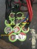
just re packed a bottle battery and fitted a new motor to an old Cytronex Cannondale bike
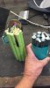
Battery is NiMh about 3.6Ah 30s1p 18660 sized cells

Motor was rusted up , but did run ..but noisy and often slipped as the internals were ..knackered

Fixed that but battery was just about dead..some dead cells. So bought new cells..re packed it and all was good..or so it seemed. volts out of the output pins

But plug it in to the bike..the bike control button lights up, the headlight works, but motor does not run when the pedals are turned. it used to before battery repack, hmmm

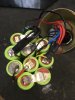
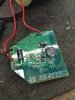
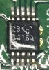
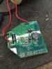
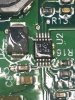
I see there is a PCB in the battery but not connected to the cells apart from the ground wire.

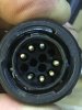
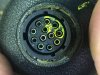
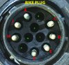
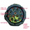
A three wire PCB..ground and V In and V out, both those wires go off up to the bottle battery connector to the controller.

Probing the wires shows zero volt on the pins when connected to the controller.

There is NOT A BMS PCB..it is NiMh not lipo, so what is this weird PCB doign ..DC Dc convertor?


Any one any idea what it is ...photos to come in following post


Owner just spent £400 on new battery cells and new motor ..and now it still won't go ....any ideas?
 
Last edited:

NeilP

Pedelecer
Sep 25, 2010
177
4
cells were identical physical size 18660, 4.5 Ah NiMh, (Sanyo SDK I think the new ones are.

Have now attached photos here.
My work is emergency ambulance stuff, so I had to just run earlier when I started this post. I am now in Oxford waiting now for medical team to get back.

I will post closer pics of IC2 later when I get home
 

Attachments

Last edited:

Nealh

Esteemed Pedelecer
Aug 7, 2014
20,139
8,233
60
West Sx RH
Is the pcb an internal Nimh charging board ?
 

NeilP

Pedelecer
Sep 25, 2010
177
4
No , charger connects just to the three central triangle of pins. One pin goes via thermistor to ground, one direct to ground, and the third positive via a £ amp fuse.

The PCB red wires connect to two pins, opposite each other and go to controller.

Unfortunately can’t get the socket out of the metal ‘bottle’ top. Will try a bit of heat tomorrow
Convinc d it is a connection issue, but can’t get to the pins

Board seems very much like a dc-dc convector. Maybe no 5 v reg in the controller ?

Will expect to find. Power in to it, back down from controller.

I am
Typing this on iPhone screen, and scrolling it induch a way that the keyboard is hiding what ib
Typing... bloody iphonex
 

Attachments

D

Deleted member 25121

Guest
Board seems very much like a dc-dc convector. Maybe no 5 v reg in the controller ?

Will expect to find. Power in to it, back down from controller.
Good idea to test it. It looks like a low current DC-DC converter to me, as you say, but those unused pads at the bottom of the photo are puzzling, maybe it's just a general purpose pcb and not specific to this ebike application. I think the 10 pin IC is labelled 5416A in which case it's a:
TPS54160ADGQ . - DC-DC Switching Buck (Step Down) Regulator, Adjustable, 3.5V-60Vin, 800mV-58Vout, 1.5Aout
which makes sense.


NeilP

Pedelecer
Sep 25, 2010
177
4
You did well to read that
!
I went back down the shed last night and tried to read with magnifier and take more photos.. Yes, think you got it

During the night I had two thoughts....

1) Is the PCB maybe the voltage reducer for the built in headlight system, and therefore normally un-powered. Will go and power on the lights and see if it Powers up

2). I have not connected the front brakes yet. There is probably a brake cut out switch that is active... and that is why motor not running. The unpowered PCB just being a red herring...

Will update in an hour or so
 

Attachments

NeilP

Pedelecer
Sep 25, 2010
177
4
OK, so
PCB, yes it was DC-DC convertor, and it did not have power on it, because it only gets power on it when the lights are turned on from the handle bar switch, so yes it is a voltage dropper for the headlights..a red herring as to why the bike was not working.

The brake that was not connected that was not the issue either as it had no brake cut out switch that I could see, but when I spun up the pedals this morning the motor ran. Only different thing I did was put the bike in to the highest (hardest to pedal) gear. Bike was on a stand with wheel in the air.

So all good. bike now working. Took it for a ride and ...no power..so intermittent issue.

had a look ar round ...Ah..rear brake lever has magnetic reed switch under the lever. flick of the bak clever and all was good.


I'll attach my scans of my sketches of the pinout of the 12 pin battery socket, the bike plug and the charger for any ones future reference.
 

Attachments

D

Deleted member 25121

Guest
Pleased to hear that all is resolved, thanks for posting the resolution on here for others to see.
 

Advertisers