Cytronex kit works for 2 revs, then cuts out for 10 secs. Pt.2

Slimjim

Pedelecer
Aug 28, 2016
56
3
50
Doncaster
I thought it tidier to start a fresh thread, as my first post was full of my random guesses, and some very useful advice from Alan, Neal and D8ve in response to my random guesses.

Following some more research/investigations, and a few hours of fiddling yesterday, I can add a few more facts which will hopefully be helpful in diagnosing the issue.

I've uploaded a short video of the symptoms to Youtube, link = https://youtu.be/fqnNW_izFBk

Basically, regardless of what I try, measure, connect, disconnect, the motor cuts in for one or two secs, the cuts out for ten secs, the cuts in for one-two secs etc etc.
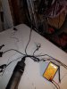
The DVM in the vid shows PCB-level DC voltage - interestingly you can see that something is still applying a load to the DC/battery supply even when the motor is not spinning, which implies that the controller is trying to turn the motor.

I'm a (mechanical) engineer, hence I'm keen to understand the system (and the 'fault' rather than just spend money on new controller, now motor, or new battery at this stage)

Summary of the facts (now that I've followed the advice of the knowledgeable people and actually checked things), in no particular order:

  1. I've now removed the wiring from the plastic trunking as it was hard to see what was connected, plus I want to turn this into a front-mounted, quick remove system so will tidy the wiring and rebag.
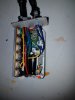
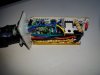
  2. I've carefully removed all of the silicone sealant that had been enthusiastically used to seal the wiring into the controller, and removed the PCB intact from the casing
  3. During tests I've measured the DC voltage of the NiMh battery - after sitting fully charged for a night, voltage measured at the external wiring was around 50V at no load, and 46V when the motor span. This seemed high for a 36V system - no load voltage on the mains chargers was >50V. After a few tests of the motor, DC voltage (now being measured at the PCB as per video was 36V at no load, dropping to ~32V when the motor kicks in. (And still bouncing even when the motor stops for ten seconds). So I don't seem to be hitting the 30V min voltage safety cutoff, but LSDZS/Lishui state that they use a 'soft' ramp-down when voltage drops towards min threshold, so maybe this is what's happening. Voltage does seem to drop significantly considering there is very little load with the bike off the ground - hopefully this does not mean that the battery is dying...?
  4. There is one red LED on the controller, which flashes continually on/off about once-per-second whenever the battery is connected, and this sequence never varies or stops
  5. I couldn't find any info online using the product IDs on the controller sticker, but the PCB is marked 'www.lsdzs.com' and their website shows at least one controller (LD-LS01-F..) that looks similar, but no user guides. There are a series of articles in the Services section that describe controller operation principles.
  6. I also can't find any details of the 'Outrider 180W 175rpm' hub motor online, but according to various posts, both the motor and controller are from 'Tongxin'.
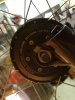
  7. The motor is sensorless - i.e. it only has 3-pins in the connector.
  8. But there are three magnets glued to one end face of the hub, opposite side to the disk brake
  9. These magnets were sensed by a black 'hall effect' - i.e. a plastic cased, 3-wire sensor, that looks like a PAS sensor, but in a black case. I have had to tape this to the (suspension) forks ends on the new bike, as the original bracket was designed to mount on mud-guard fixings, which these forks don't have. The sensor is at most 1mm from the magnets as they rotate past.
  10. I still can't figure out what these magnets are for - as far as I know, a sensorless controller measures phase back-EMF to determine rotor position, it does not require an additional sensor inputs.
  11. However, I believe that sensorless motors cannot normally start from standstill, they need rotation and back-EMF to determine rotor position, whereas this system will spin-up from standstill, as per video
  12. If the three external hub magnets ARE used for motor control, then in theory the position of the black sensor needs to be set accurately, as otherwise the controller does not know where the sensor is relative to the axle/stator installation angle, as this varies with the angle of whichever fork is fitted, and therefore the original backet must be designed for the original Charge forks?
  13. Measuring signal voltage on the PAS, I saw (with my cheap DVM), the signal rise to ~4.6V whenever a magnet passed as I span the cranks
  14. The original black fork sensor did not show any measurable response to hub magnets passing, and the new sensor I bought and tried yesterday (which is actually a read-cased PAS sensor, but the only type I could buy), only registers a ~0.5V rise in signal when a magnet passes (with sensor <1mm from magnet) therefore possibly the new sensor is also faulty, or the circuit is faulty
  15. Regardless of what I try/connect/disconnect etc, the effects are always the same – as per video I just get intermittent hub rotation.
  16. I can’t test any of this on a rolling bike yet, as none of the brackets for the sensors fit my bike
  17. I did speak to Gibbs at Cytronx yesterday, but although he was helpful, he was not able to tell me much as the system set up is proprietary, and part of their business is the custom installation of kits so understandably he doesn’t want to give away their secrets.

So my main question for now is – is the fork sensor used to control motor operation? I.e. have Cytronex invented their own external hall-effect sensor system, in conjunction with the original sensorless motor/controller?

If so then I’ll continue trying to set that up correctly through trial-and-error angular position.

If not, then is the controller, motor, or battery fried…?

Thanks in advance as always!

Adam
 

Alan Quay

Esteemed Pedelecer
Dec 4, 2012
2,351
1,076
Devon
I think I have a spare KU65. If you want I'll send it over. (I'll check in the next couple of days)

You'll be able to eliminate the sensors and controller that way.

I don't know for sure that this motor will work with it, but it's worth a go. I'll send a throttle as well.

D8veh can probably confirm, but I've found the humble KU65 to be the most compatible controller.
 

Slimjim

Pedelecer
Aug 28, 2016
56
3
50
Doncaster
I think I have a spare KU65. If you want I'll send it over. (I'll check in the next couple of days)

You'll be able to eliminate the sensors and controller that way.

I don't know for sure that this motor will work with it, but it's worth a go. I'll send a throttle as well.

D8veh can probably confirm, but I've found the humble KU65 to be the most compatible controller.
That would be great Alan, I actually work with a few motor and electronics gurus so I'm planning to take the kit in and see if I borrow scopes, decent DVM etc to see what's going on. I'm just intrigued to know what the extra glued-on magnets are for.

But a loan controller (or if it solves the problem and you want to sell it) would be great to at least rule out battery and motor as the problem.


I can see this becoming an expensive habit longer term - this kit was donated to me by my brother, so not the end of the world if for example the battery is dead.

However as a lapsed mountain biker, I'm now looking at the higher power kits. But an imminent house/county move, and a wife who's had enough of me buying expensive gadgets, means it would be great if I can get this kit working without investing a huge amount, other than time.

I'm currently tidying up the wiring harness and trying to fit everything into a small top-tube bag to make it all easily removed for off-roading when i refit the original un-powered front wheel. I'll probably need to fashion an air-cooled heatsink on the outside of the bag, as with a relatively modest output I'm assuming that the system is going to be working fairly hard under load.
 
D

Deleted member 4366

Guest
That's a standard Li Shui sensorless controller.

A KU65 should be able to sort it out.

Sensorless controllers can start the motor without positional sensors.

What is the sensor that uses those three magnets connected to?

If those magnets and sensor are used for determining the motor position, the location of the sensor would be critical. You can't just put it anywhere.
 

Slimjim

Pedelecer
Aug 28, 2016
56
3
50
Doncaster
That's a standard Li Shui sensorless controller.

A KU65 should be able to sort it out.

Sensorless controllers can start the motor without positional sensors.

What is the sensor that uses those three magnets connected to?

If those magnets and sensor are used for determining the motor position, the location of the sensor would be critical. You can't just put it anywhere.
That's exactly my thinking D8ve.

The wiring from the fork sensor connects directly to the control PCB, a couple of holes away from the PAS sensor.

The issue that occurred to me is that the angular alignment of the stator is determined by the axle, which keys into the fork dropouts. Hence the steel bracket that held the fork sensor on the original Charge forks, when installed by Cytronex, must have placed the sensor in the right angular position relative to the default angle of the stator. There is no angular adjustment possible with the bracket - i.e. no adjustment slots. There other option is that Cytronex effectively adjust the timing of the hall effect signal relative to the back EMF waveform of the motor on each bike during installation. Which isn't impossible, I've worked on larger permanent magnet motors with rotor position sensors that needed to be 'timed' mechanically during motor assembly, or by adjusting the electronic timing in the controller.

I'm just interested to know if this is what Cytronex do, if so presumably to avoid the fragility of internal hall effect in the motor, but to still allow operation from zero speed.

That's why I'm planning to make a little test rig/bracket that will allow me to adjust the angular position of the fork sensor to find a position that works. Ideally I'd measure my brother's Charge forks, but he lives a few hundred miles away.

Or possibly I'm barking up the wrong tree...
However, the magnets have been glued on for a reason, and from the photos on Cytronex website it looks like all their bikes have these.

Could always be for a computer I guess, but you wouldn't need three magnets, odometers normally work off one magnet?
 

Slimjim

Pedelecer
Aug 28, 2016
56
3
50
Doncaster
I was told that crank PAS sensor is used by controller for 'Speed advance' but couldn't figure out how that would work, as these bikes have multiple gears so there isn't a constant ratio between crank and wheel rpm.

Unless the controller simply applies more voltage/current to accelerate the motor when it detects an increase in crank speed, regardless of actual crank speed.

I'm not sure how these sensorless pedelecs systems work though, I assumed they just tried to apply full torque/power to assist, and the eventual speed just depended on the prevailing road load, up to maximum wheel speed.

The Cytronex guys obviously know what they're doing though, so I may well have misunderstood what I'm looking at.
 

Alan Quay

Esteemed Pedelecer
Dec 4, 2012
2,351
1,076
Devon
I have just got back from post office.

I have sent:

KU65 controller and display
Throttle
5 test leads

When you get it:

With the bike upside down or wheel othwise off ground.

1. Connect throttle and display to controller
2. Connect controller phase wires to motor phase wires (3 fat ones) with the three test leads. Be sure the exposed conductive parts can't touch each other.
Try to match colours, but it may not natter too much.
3. Connect black/red test leads to to controller black/red, then finally to battery (don't let them touch!)
4. Switch on controller from the display.
5. Gently apply a little throttle, listen for horrid noises and look out for smoke!

Report back result here.

(Note, the test leads are very thin, but this is fine for non-load testing. I've used them many times no problem just keep an eye on them and don't go running the motor for minutes at a time)
 

Slimjim

Pedelecer
Aug 28, 2016
56
3
50
Doncaster
I have just got back from post office.

I have sent:

KU65 controller and display
Throttle
5 test leads

When you get it:

With the bike upside down or wheel othwise off ground.

1. Connect throttle and display to controller
2. Connect controller phase wires to motor phase wires (3 fat ones) with the three test leads. Be sure the exposed conductive parts can't touch each other.
Try to match colours, but it may not natter too much.
3. Connect black/red test leads to to controller black/red, then finally to battery (don't let them touch!)
4. Switch on controller from the display.
5. Gently apply a little throttle, listen for horrid noises and look out for smoke!

Report back result here.

(Note, the test leads are very thin, but this is fine for non-load testing. I've used them many times no problem just keep an eye on them and don't go running the motor for minutes at a time)
That's great. Many thanks Alan.

I will follow your instructions and try not to blow anything up!
 

Slimjim

Pedelecer
Aug 28, 2016
56
3
50
Doncaster
Bit of an update: Everything arrived intact - thanks Mike for the loan.

I managed to get everything carefully wired up, with electrical tape over all exposed connections, as per instructions.

Can't seem to get any response from the throttle - measuring 36.9v at controller input, phase colours match, and I've tried spinning front wheel just in case the controller needs to see back EMF.

Tried all three power settings, and the Walk function.

Also can't hear any evidence that controller is trying to push current. I didn't see any change in DC voltage - I.e. no indication that the controller was trying to push current into the windings.

I've been called in for my tea now so I'll try again tomorrow night. Do you think I to link out any inputs?

Or spin the front wheel for longer?

I'll recheck all wiring, and see if I can measure rms phase voltage with my cheapo DVM.

Cheers, Adam
 

Alan Quay

Esteemed Pedelecer
Dec 4, 2012
2,351
1,076
Devon
Ignition wire shouldn't be required, as he has a n led display.

You may have to try all combinations of the phase wires, then apply a little throttle each time. There will be 6 possible combinations so it's best to write them down and tick them off.

Good luck.
 
  • Like
Reactions: Slimjim

Slimjim

Pedelecer
Aug 28, 2016
56
3
50
Doncaster
Ignition wire shouldn't be required, as he has a n led display.

You may have to try all combinations of the phase wires, then apply a little throttle each time. There will be 6 possible combinations so it's best to write them down and tick them off.

Good luck.
Will do tonight or this weekend, cheers
 
D

Deleted member 4366

Guest
AFAIK the KU65 has automatic detection and setting of phase sequence and angle. The first thing to check after switching on is that you have 5v between the throttle red and black wires, then check between the black and signal wire to see that the signal varies between 1 and 4 volts.

I doubt that you'll be able to measure anything on the phase wires because the controller sends out an initialisation sequence. If it doesn't detect the right response, it stops PWM. If you had an ebike tester, you'd be able to see it. Also, at any time, if the controller doesn't get the correct back emf or hall signal, it shuts down power.

http://www.ebay.co.uk/itm/Portable-24V-36V-48V-60V-Electro-Car-E-bike-Vehicle-Brushless-Tester-24V-to-60V-/262581405038?hash=item3d2312456e:g:m4gAAOSw9NdXs~tI
 

Slimjim

Pedelecer
Aug 28, 2016
56
3
50
Doncaster
AFAIK the KU65 has automatic detection and setting of phase sequence and angle. The first thing to check after switching on is that you have 5v between the throttle red and black wires, then check between the black and signal wire to see that the signal varies between 1 and 4 volts.

I doubt that you'll be able to measure anything on the phase wires because the controller sends out an initialisation sequence. If it doesn't detect the right response, it stops PWM. If you had an ebike tester, you'd be able to see it. Also, at any time, if the controller doesn't get the correct back emf or hall signal, it shuts down power.

http://www.ebay.co.uk/itm/Portable-24V-36V-48V-60V-Electro-Car-E-bike-Vehicle-Brushless-Tester-24V-to-60V-/262581405038?hash=item3d2312456e:g:m4gAAOSw9NdXs~tI
Hi Mike and D8ve, sorry had a hectic few days so didn't get a chance to carry out any more tests. I'll measure throttle voltage etc tomorrow evening and report back, thanks for the advice and patience.
 

Slimjim

Pedelecer
Aug 28, 2016
56
3
50
Doncaster
Finally got a chance to carry out some more tests today, apologies for hanging onto your loan kit Mike for longer than expected.

Dave, with battery at about 36v, I've got 4.3v as the throttle. Throttle signal measures 3.5v when throttle is fully off, dropping to 0.7v at full throttle.

At a signal level below about 3v (approx 1/3 twist) the motor kicks smoothly in either low, medium or high power setting. As before the motor spins for about 1/3 rev before cutting out.
If i keep the throttle more then 1/3 open, the motor kicks repeatedly for 1/3 rev, then cuts out, then cuts in after 1-2secs for another 1/3 rev etc etc.

Battery voltage (measured with a cheap DVM that is showing average voltage and I don't know what the refresh rate is), shows that voltage generally stays above 32v, but occasionally drops below 30v. However DVM reports voltage as being above 32v for most of the time, during which the motor is kicking on/off.

I'm starting to suspect that the battery is weak, and the refresh rate on my DVM is to slow to show this.
Does the SKU65 drop out immediately when voltage hits 30v, or does it have a soft ramp down from say 32v?

I'm going to try to get to kit set up on a test bench at work and either use a scope to measure battery voltage with a suitable high frequency, or try pressing the kit from a bench top power supply.

In the meantime I'll leave the battery on an overnight charge and try again tomorrow.

Does that sound sensible?

Cheers, Adam
 

Advertisers