Battery Extender
Continuing with the experiences and learning of the Orbea Gain D50, I have come to the conclusion that it will not be bad to have a battery extension system. We have optimized the administration of the energy available in the main battery to the maximum, we have gotten physically fit, we have reduced our mass and that of the ebike as much as possible, but now we want to make long-lasting and more demanding routes, and always count on our support levels.
It is in these cases where we need an additional battery.
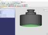
Mahle/Orbea has developed its own battery extender, and I'll start by summarizing its features:
Total capacity: 208.8W/h (5.8A)
Voltage: 36 V
Cells: Panasonic
Charging time: 3 hours
Maximum discharge ratio: 1.9 A
Water resistance: IP57
Color: Anodized black
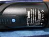
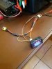
Charging and ignition display: Iwoc One button Charging port protected by a rubber cover.
Dual charging: The Range Extender and main battery can be charged at the same time by connecting the Range Extender to the main battery and the X35 charger to the Range Extender.
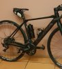
Certifications: EN 15194.2017 Bicycle mounting: Specific X35 bottle holder with Quick Lock rubber band. Exclusive mounting on the seat tube *(diagonal tube on the Optima).
Weight: 1645 g with bottle holde

The Mahle Range Extender works like a portable internal battery charger that charges the main battery while it is turned on. It operates differently from other systems in that on the Ebikemotion X35, only the main battery provides power to the motor, while the Range Extender charges the main battery, regardless of whether the motor demands current from the main battery or not (such as at speeds greater than 25 km/h, when there is no pedaling or the bicycle is not moving).
The Range Extender provides charge to the main battery at a discharge ratio of 2A, while the motor can demand current of up to 9A. Therefore, the Range Extender is not capable of supplying enough current to the motor by itself, and all this current comes from the main battery.
So far so good and very nice, but 1) the price of this battery extender is extremely high 2) they are not available on the market today.
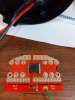
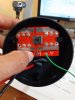
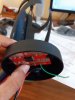
This has motivated many desperate enthusiasts like me to look for a DIY solution.
Of all that I have read and seen on the web, Yako's experiments (see attached YouTube link) are the ones that have shown a functional and tested DIY system.
Allow me to make an explanatory summary about the Mahle extender system and the options we have when building a DIY extender. These conclusions that I will summarize are the result of my careful analysis of the Mahle and Orbea specifications on their battery extender. As a professional I start from the premise that a serious manufacturer does not lie in its specifications.
The Mahle extender is designed to behave like a main battery charger, supplying only 2 Amps of charging current and a voltage that will depend on the level of charge remaining in the extender. It means that in its electronics, the extender includes a current limiter at 2amps max. and also a reverse current block device to prevent the main battery charging the extender. In other words, it is a system equivalent to the 110/220 VAC ---> 42VDC 2Amp charger that we use to charge the main battery at home.
The question that arises at this point is why only 2 amps does the Mahle extender deliver? What's wrong with that? I'd say there's a lot of good in it. I explain.
A battery bank in a 10S2P arrangement, as is the case, requires 2Amp max as recommended for charging. So far the Mahle system is doing well, because the extender system marketed by a manufacturer must be safe and easy to use by any user and in any condition (this will be better understood when I explain the operation of a DIY extender).
Let's remember a basic principle of the theory of movement of charges: for there to be an electric current (movement of electric charges) from point A to point B, point A must be at a higher potential (voltage) than point B. Keeping this in mind, let's assume that the Mahle extender is point A and the internal battery is point B, and that they are fully charged (same voltage, so no current from the extender to the main battery).
The trip begins and we begin to demand assistance from the Ebike, the motor begins to consume energy. From where? From the main battery and the battery extender. But with one big limitation: the extender will never deliver more than 2 amps. Suppose the assistance level demands 4 amps (which is a lot: 4x36=144 W), 2 amps will come from the main battery and 2 from the extender, and both systems are discharged equally at the same voltage. We stop pedaling: nothing happens since there is no difference in potential between both systems, both are at the same level of charge, there are no currents.
Now, what happens if at that moment (both batteries are equalized in voltage) the level of assistance required is so great that it demands 200W ( 200/36=5.6 Amps). For this demand, 3.6 Amps will come from the main battery and only 2 Amps from the extender. The main battery begins to discharge faster than the extender and at the end of that demand we stop pedaling, we will have the main battery more discharged than the extender, that is, there is a difference in potential and the extender begins to charge the main battery at a rate of 2 amps max. only. It may happen that it fully charge it, or that it charges it just a little, because another request for assistance may occur and the differences in potential will never be the same.
As I've mentioned, and this is a very personal conclusion I've come to, the Mahle Battery Extender was designed to function similar to a battery charger with current limiting at 2 amps. Why so? Because it is the safest and easiest way to use by anyone, at any time and without having to take any precautions (plug and play). As the main battery is the one that provides the greatest load demand to the engine, the extender will always go behind the main battery trying to charge it (at times when there is no load demand from the main battery.)
Do they work in parallel? Yes, at times when the motor demands current.
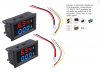
Now let's see what a DIY extender could look like:
1) Like the Mahle, with the main battery charger concept and current limitation always at 2amps.
2) As an additional battery in parallel and with the same current contribution to the load as the main battery. No charger approach.
Why approach 2 is not commonly used? Because it's complicated, risky, and somewhat impractical to use commercially. Not all users would be willing to learn how to use it and it could lead to lawsuits against the manufacturers that market it.
The operating principle of approach 2 is based on the use of 2 battery banks as equal as possible. That is, equal current capacity, equal voltage, equal cell technology. In our case they will be 250Wh 10S2P battery banks. Built from basic Panasonic 18650 cells. One of these banks is just the main battery, the other the extender.
If both batteries are charged to 100% and separately, in theory they will each have the same open circuit voltage. If under these conditions we connect them in parallel, the resulting voltage will be the same and since there is no potential difference between them, there will be no transient current from one battery to the other. The parallel bank will maintain the same voltage while there is no load.
When the motor demands current, that current will be supplied in equal parts by the main and the extender (either high current or low). What happens to the parallel voltage of the bank? Well, go down as current is demanded. One battery charges the other? No. Both batteries are discharged equally until reaching the protection cutoff limit of each of them.
What happens if this procedure is not strictly followed?
Continuing with the experiences and learning of the Orbea Gain D50, I have come to the conclusion that it will not be bad to have a battery extension system. We have optimized the administration of the energy available in the main battery to the maximum, we have gotten physically fit, we have reduced our mass and that of the ebike as much as possible, but now we want to make long-lasting and more demanding routes, and always count on our support levels.
It is in these cases where we need an additional battery.
Mahle/Orbea has developed its own battery extender, and I'll start by summarizing its features:
Total capacity: 208.8W/h (5.8A)
Voltage: 36 V
Cells: Panasonic
Charging time: 3 hours
Maximum discharge ratio: 1.9 A
Water resistance: IP57
Color: Anodized black
Charging and ignition display: Iwoc One button Charging port protected by a rubber cover.
Dual charging: The Range Extender and main battery can be charged at the same time by connecting the Range Extender to the main battery and the X35 charger to the Range Extender.
Certifications: EN 15194.2017 Bicycle mounting: Specific X35 bottle holder with Quick Lock rubber band. Exclusive mounting on the seat tube *(diagonal tube on the Optima).
Weight: 1645 g with bottle holde
The Mahle Range Extender works like a portable internal battery charger that charges the main battery while it is turned on. It operates differently from other systems in that on the Ebikemotion X35, only the main battery provides power to the motor, while the Range Extender charges the main battery, regardless of whether the motor demands current from the main battery or not (such as at speeds greater than 25 km/h, when there is no pedaling or the bicycle is not moving).
The Range Extender provides charge to the main battery at a discharge ratio of 2A, while the motor can demand current of up to 9A. Therefore, the Range Extender is not capable of supplying enough current to the motor by itself, and all this current comes from the main battery.
So far so good and very nice, but 1) the price of this battery extender is extremely high 2) they are not available on the market today.
This has motivated many desperate enthusiasts like me to look for a DIY solution.
Of all that I have read and seen on the web, Yako's experiments (see attached YouTube link) are the ones that have shown a functional and tested DIY system.
Allow me to make an explanatory summary about the Mahle extender system and the options we have when building a DIY extender. These conclusions that I will summarize are the result of my careful analysis of the Mahle and Orbea specifications on their battery extender. As a professional I start from the premise that a serious manufacturer does not lie in its specifications.
The Mahle extender is designed to behave like a main battery charger, supplying only 2 Amps of charging current and a voltage that will depend on the level of charge remaining in the extender. It means that in its electronics, the extender includes a current limiter at 2amps max. and also a reverse current block device to prevent the main battery charging the extender. In other words, it is a system equivalent to the 110/220 VAC ---> 42VDC 2Amp charger that we use to charge the main battery at home.
The question that arises at this point is why only 2 amps does the Mahle extender deliver? What's wrong with that? I'd say there's a lot of good in it. I explain.
A battery bank in a 10S2P arrangement, as is the case, requires 2Amp max as recommended for charging. So far the Mahle system is doing well, because the extender system marketed by a manufacturer must be safe and easy to use by any user and in any condition (this will be better understood when I explain the operation of a DIY extender).
Let's remember a basic principle of the theory of movement of charges: for there to be an electric current (movement of electric charges) from point A to point B, point A must be at a higher potential (voltage) than point B. Keeping this in mind, let's assume that the Mahle extender is point A and the internal battery is point B, and that they are fully charged (same voltage, so no current from the extender to the main battery).
The trip begins and we begin to demand assistance from the Ebike, the motor begins to consume energy. From where? From the main battery and the battery extender. But with one big limitation: the extender will never deliver more than 2 amps. Suppose the assistance level demands 4 amps (which is a lot: 4x36=144 W), 2 amps will come from the main battery and 2 from the extender, and both systems are discharged equally at the same voltage. We stop pedaling: nothing happens since there is no difference in potential between both systems, both are at the same level of charge, there are no currents.
Now, what happens if at that moment (both batteries are equalized in voltage) the level of assistance required is so great that it demands 200W ( 200/36=5.6 Amps). For this demand, 3.6 Amps will come from the main battery and only 2 Amps from the extender. The main battery begins to discharge faster than the extender and at the end of that demand we stop pedaling, we will have the main battery more discharged than the extender, that is, there is a difference in potential and the extender begins to charge the main battery at a rate of 2 amps max. only. It may happen that it fully charge it, or that it charges it just a little, because another request for assistance may occur and the differences in potential will never be the same.
As I've mentioned, and this is a very personal conclusion I've come to, the Mahle Battery Extender was designed to function similar to a battery charger with current limiting at 2 amps. Why so? Because it is the safest and easiest way to use by anyone, at any time and without having to take any precautions (plug and play). As the main battery is the one that provides the greatest load demand to the engine, the extender will always go behind the main battery trying to charge it (at times when there is no load demand from the main battery.)
Do they work in parallel? Yes, at times when the motor demands current.
Now let's see what a DIY extender could look like:
1) Like the Mahle, with the main battery charger concept and current limitation always at 2amps.
2) As an additional battery in parallel and with the same current contribution to the load as the main battery. No charger approach.
Why approach 2 is not commonly used? Because it's complicated, risky, and somewhat impractical to use commercially. Not all users would be willing to learn how to use it and it could lead to lawsuits against the manufacturers that market it.
The operating principle of approach 2 is based on the use of 2 battery banks as equal as possible. That is, equal current capacity, equal voltage, equal cell technology. In our case they will be 250Wh 10S2P battery banks. Built from basic Panasonic 18650 cells. One of these banks is just the main battery, the other the extender.
If both batteries are charged to 100% and separately, in theory they will each have the same open circuit voltage. If under these conditions we connect them in parallel, the resulting voltage will be the same and since there is no potential difference between them, there will be no transient current from one battery to the other. The parallel bank will maintain the same voltage while there is no load.
When the motor demands current, that current will be supplied in equal parts by the main and the extender (either high current or low). What happens to the parallel voltage of the bank? Well, go down as current is demanded. One battery charges the other? No. Both batteries are discharged equally until reaching the protection cutoff limit of each of them.
What happens if this procedure is not strictly followed?