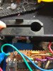
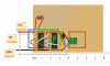
So here's what the circuit looks like. When I get a bit more time i'll sort a proper schematic out. But based on this diagram you should be able to work it out. The VCC needs 5v. I havnt bothered building in a switch since the whole circuit takes such little power its not worth it.
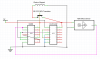
Here's some links to the IC's I used:
4013 D-Type Flip Flop http://www.electroschematics.com/6509/4013-datasheet/
4093 NAND http://www.electroschematics.com/6454/ic-4093-datasheet/
Here's some links to the IC's I used:
4013 D-Type Flip Flop http://www.electroschematics.com/6509/4013-datasheet/
4093 NAND http://www.electroschematics.com/6454/ic-4093-datasheet/


![20170526_173329[1651].jpg](/forum/data/attachments/17/17264-57d9ebecf6fda50a9b4f8b16e5565bbf.jpg)
![20170526_173617[1752].jpg](/forum/data/attachments/17/17265-8efd6825e9876ad63e85ab58394d7aa2.jpg)
![20170526_173012[1650].jpg](/forum/data/attachments/17/17263-f0e2134eccb93c0d4cff644b27e9e3fc.jpg)