

Awesome! Let me know if you need any of the 3d files. I'll be uploading them to thingiverse soon and ill post the link there when im done. I'll also update my first post with my new design.Thanks for all that. As an added bonus looks like I'll get my new 3D printer in on the act!
Ebike derestrictor
- Thread starter Festivejelly
- Start date
Thanks, but I've got a more immediate issue. Just been checking my wifes Gazelle Innergy bike - no magnet on the wheel - I am now worried that the speed sensor is internal in the front wheel motor. May need to do some investigative dismantling!Awesome! Let me know if you need any of the 3d files. I'll be uploading them to thingiverse soon and ill post the link there when im done. I'll also update my first post with my new design.
Thanks for sharing your schematics.
I didn't see but did you post a schematic for the ATTiny85 version?
Did you only need to use a single AA battery for this version?
I didn't see but did you post a schematic for the ATTiny85 version?
Did you only need to use a single AA battery for this version?
D
Deleted member 4366
Guest
You can run these micro-processors from the 5v in the motor hall or speed sensor wires, which saves a lot of messing about.
This is a circuit that works well for me. I tried the external coil/relay first, but it was taking too much power plus bulky. It is on bosch performance line 2015 which uses reed switch instead of hall sensor.
Attachments
-
 22.4 KB Views: 242
Would anyone be willing to build one of these for a carrera vulcan e spec? It would have to spoof speed signal through the motor wire as the sensor is hidden away inside. Would pay good money for a device that goes between the motor connectors and frees the bike.
Currently own a crossfuse e with a bosch mid drive active line plus motor...anybodyhappy to help me with a part list and mini guide i guess for this? Appreciate it thanks
https://www.ebiketuning.com/shop/bosch-gen2.htmlCurrently own a crossfuse e with a bosch mid drive active line plus motor...anybodyhappy to help me with a part list and mini guide i guess for this? Appreciate it thanks
I've figured out how to get the maximum speed raised 4% to 25.9km/h ....the Bosch computer can have it's wheel circumference dropped from the correct 2220mm to 2137mm, which I was disappointed to find was as low as they'd allow, I was hoping for 1110mm lol
Hey guys - a have a suggestion re batteries. You can pick up a solar panel for about US60 cents at AliExpress: https://www.aliexpress.com/item/ANBES-Solar-Panel-5V-6V-12V-Mini-Solar-System-DIY-For-Battery-Cell-Phone-Chargers-Portable/32848710253.html?spm=a2g0s.9042311.0.0.27424c4dACxKDX
Then one of these bad boy solar chargers for US1.40: https://www.aliexpress.com/item/Mini-Solar-Lipo-Charger-Board-CN3065-Lithium-Battery-Charge-Chip-DIY-Outdoor-Application-Kit-Charging-Board/32877873848.html?spm=a2g0s.9042311.0.0.27424c4dACxKDX
I've bought both and tested them - they work brilliantly together.
The solar panel pushes out up to 6v at 1.5w. With any LiPo or Li-Ion attached, like a 18650 it will run for up to 8 years (I checked this with a friend who's an electronic engineer). The life basically comes down to the life of the battery itself and whether it likes to be topped-up or not (check out the differences between LiPo and Li-Ion). The solar panel is small and can be mounted anywhere. I've 3D printed a casing for mine, and it looks great. The solar charger contains a voltage regulator, so if you want you can remove the voltage regulator from whatever arduino you are using. I use an ESP8266-12F which costs US1.39 (https://www.aliexpress.com/item/new-ESP8266-Remote-Serial-Port-WIFI-Transceiver-Wireless-Module-Esp-12F-AP-STA/32633529267.html?spm=a2g0s.9042311.0.0.27424c4d3dG84f) because it's the same as a Wemos D1 without the LED and voltage regulator so it uses hardly any power. It also means you can program it over the air (OTA) as it's got built in wifi.
I'm in Australia so there is plenty of sunshine to keep the battery charged. If you live somewhere with not so much sunlight, the solar charger contains a micro USB cable to manually charge the battery. You MAY have to do that once every year or two for a few hours.
So, battery problem solved!
Good information for general Arduino applications, but it seems like a complicated solution for an ebike derestrictor when you can mount the Arduino in the motor cable and use the 5v that's provided for the hall sensors. You can buy a motor extension cable, cut off the connectors and make a self-contained unit that fits between the two motor connectors.Hey guys - a have a suggestion re batteries. You can pick up a solar panel for about US60 cents at AliExpress: https://www.aliexpress.com/item/ANBES-Solar-Panel-5V-6V-12V-Mini-Solar-System-DIY-For-Battery-Cell-Phone-Chargers-Portable/32848710253.html?spm=a2g0s.9042311.0.0.27424c4dACxKDX
Then one of these bad boy solar chargers for US1.40: https://www.aliexpress.com/item/Mini-Solar-Lipo-Charger-Board-CN3065-Lithium-Battery-Charge-Chip-DIY-Outdoor-Application-Kit-Charging-Board/32877873848.html?spm=a2g0s.9042311.0.0.27424c4dACxKDX
I've bought both and tested them - they work brilliantly together.
The solar panel pushes out up to 6v at 1.5w. With any LiPo or Li-Ion attached, like a 18650 it will run for up to 8 years (I checked this with a friend who's an electronic engineer). The life basically comes down to the life of the battery itself and whether it likes to be topped-up or not (check out the differences between LiPo and Li-Ion). The solar panel is small and can be mounted anywhere. I've 3D printed a casing for mine, and it looks great. The solar charger contains a voltage regulator, so if you want you can remove the voltage regulator from whatever arduino you are using. I use an ESP8266-12F which costs US1.39 (https://www.aliexpress.com/item/new-ESP8266-Remote-Serial-Port-WIFI-Transceiver-Wireless-Module-Esp-12F-AP-STA/32633529267.html?spm=a2g0s.9042311.0.0.27424c4d3dG84f) because it's the same as a Wemos D1 without the LED and voltage regulator so it uses hardly any power. It also means you can program it over the air (OTA) as it's got built in wifi.
I'm in Australia so there is plenty of sunshine to keep the battery charged. If you live somewhere with not so much sunlight, the solar charger contains a micro USB cable to manually charge the battery. You MAY have to do that once every year or two for a few hours.
So, battery problem solved!
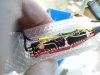
Hi Any chance to share .STL of this case Many thanks in advanceSome images here, note the attiny prototype is way smaller in size than the solution that uses Nand gates and a flipflop.
")
Hi Guys has anyone tried Attiny85 code yet? This works for about 20-30 seconds and goes off and come back On after a while for sometime etc.Arduino code:
The above includes functionality to sleep when its not detected a magnet in 30 seconds. this is there to save power. When its in sleep mode the device draws about 20 micro amps, which is a tiny amount.Code:// Nicholas John // 22 May 2017 // // ATMEL ATTINY 85 // // +-\/-+ // (PCINT5/RESET/ADC0/dW) PB5 1| |8 Vcc // (PCINT3/XTAL1/OC1B/ADC3) PB3 2| |7 PB2 (SCK/USCK/SCL/ADC1/T0/INT0/PCINT2) // (PCINT4/XTAL2/CLKO/OC1B/ADC2) PB4 3| |6 PB1 (MISO/DO/AIN1/OC0B/OC1A/PCINT1) // GND 4| |5 PB0 (MOSI/DI/SDA/AIN0/OC0A/OC1A/AREF/PCINT0) // +----+ #include <avr/sleep.h> // Sleep Modes #include <avr/power.h> #include <elapsedMillis.h> const int hallPin = 2; // the number of the hall effect pin const int magnetPin = 1; // the number of the magnet pin const long debouncing_time = 15; //Debouncing Time in Milliseconds // variables will change: volatile int hallState = 0; // variable for storing the hall counter volatile unsigned long last_micros; elapsedMillis timer; void setup() { pinMode(magnetPin, OUTPUT); pinMode(hallPin, INPUT); //digitalWrite(hallPin, HIGH); // Attach an interrupt to the ISR vector attachInterrupt(0, pin_ISR, RISING); //default interupt pin is always 0 on attiny85 (physical pin 7) timer = 0; } void sleep() { GIMSK |= _BV(PCIE); // Enable Pin Change Interrupts PCMSK |= _BV(PCINT2); // Use PB2 as interrupt pin ADCSRA &= ~_BV(ADEN); // ADC off set_sleep_mode(SLEEP_MODE_PWR_DOWN); // replaces above statement sleep_enable(); // Sets the Sleep Enable bit in the MCUCR Register (SE BIT) sei(); // Enable interrupts sleep_cpu(); // sleep cli(); // Disable interrupts PCMSK &= ~_BV(PCINT2); // Turn off PB2 as interrupt pin sleep_disable(); // Clear SE bit ADCSRA |= _BV(ADEN); // ADC on sei(); // Enable interrupts } // sleep void loop() { if(hallState>1) { digitalWrite(magnetPin,HIGH); delay(20); digitalWrite(magnetPin,LOW); hallState=0; } if(timer>=30000) { sleep(); } } void pin_ISR() { if((long)(micros() - last_micros) >= debouncing_time * 1000) { timer=0; hallState++; last_micros = micros(); } }
Also includes debounce code to handle bouncing that you'll get using a reed switch.
The First Arduino Code works perfectly fine but I couldnt manage to fix attiny85 code
Any help/advice/wiring diagram is welcome ...
Hrm I havnt tried this for a long time but I did have a solution that worked for me. Let me have a dig around my hard disk see if I still have that code.Hi Guys has anyone tried Attiny85 code yet? This works for about 20-30 seconds and goes off and come back On after a while for sometime etc.
The First Arduino Code works perfectly fine but I couldnt manage to fix attiny85 code
Any help/advice/wiring diagram is welcome ...
It could well be that your attiny85 is rebooting. Maybe its not able to draw enough power?

I've added this line its working now but not sure if it goes to sleep or not
Hi @Festivejelly @IR772
So my circuit works, but not the coil magnet.
I'm a physicist so have a calibrated Hall sensor. The magnet on the bike produces 40 to 50my at the bike sensor. The most I get out of my coil magnet with hundreds of windings, only 6mm tall to fit between spokes and sensor is 3mT with batteries, or 20mT with 30 volt per supply frying the coil!
Hard to believe a coil at 90 degrees works. Can you tell me what coil, voltage and battery source you used please? And I'll try a side mounted option.
Thanks
Attachments
-
 4.7 MB Views: 70
Hi @Festivejelly @IR772
Quick update. Just tested relay MT2-C93401 in the lab with a power supply.
I can get a field of 12mT out of that relay with a 15volt supply, which is 4 times more than I had from my drill wound option, but doesn't reach the 40-50mT at the bike's hall sensor from the bike fixed magnet.
I'll give it a go on the bike though and maybe that'll be enough running off an 18 volt power tools battery. All the ICs run up to about 40 volt I think.
I'm puzzled how either of you got enough field out of a button battery !
Thanks