Figuring out the wiring for a hall sensor

TheBikeMan

Pedelecer
Mar 23, 2018
58
1
60
Cardff UK
Hi,
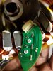
We have a Giant Twist on which we are replacing the control unit. We have a problem with wiring the hall sensor. The hall sensor wires from the bike are Black/Brown/White/Grey/Orange/Green.
The wires on the control unit are the standard stuff Black/Red/Blue/Green/Yellow.
I'm trying to figure out how to know which wire on the controller to hook to which wires on the bike. Any thoughts on how we might make this deduction?
Thanks so much for any help.
Karey
 

wheeliepete

Esteemed Pedelecer
Feb 28, 2016
2,047
755
60
Devon
Are the wires the same colour on the old controller? Looking inside, tracing where the wires are connected to the PCB may give you some clues. Looks like you have a speed sensor in the motor also, prob. the white wire. Black and brown most likely to be +/-, with the other 3 hall sensor wires.
 

Nealh

Esteemed Pedelecer
Aug 7, 2014
19,990
8,172
60
West Sx RH
I go with Pete and you will have to look on the old controller pcb to confirm all.

Match up is likely to be;
Black/ Gnd.
Brown/5v.
White speed.
Grey /Blue hall A.
Green/Green hall B.
Orange/Yellow hall C.

The last 3 are often prefixed sa or a , sb or b & sc or c on pcb and sit next to each other, if so the first three will be correct.
White speed sensor might be ss or sp prefix.
A magnifying glass will help to read any small print.
 
Last edited:

TheBikeMan

Pedelecer
Mar 23, 2018
58
1
60
Cardff UK
Hi Pete,
The wires on the old controller are the same colours as the ones coming from the motor. The speed sensor is an old style magnet job on the rear wheel. Good point about the white wire from the motor however. It made me look at the loom going from the motor to the control unit. So the wires coming out of the motor are as above but the plug that they go into does not use the green wire. The rest of the colours are the same.
 

wheeliepete

Esteemed Pedelecer
Feb 28, 2016
2,047
755
60
Devon
Ok, so you can discount the green wire then, If you can find/trace +/- on the old controller, then you can mix/match the remaining 3 until the motor runs correctly.
Is there a resistance or continuity measurement that can be done on the 3 wires to determine their wiring series?
Not as far as I know, without first determining +/-.
 

Nealh

Esteemed Pedelecer
Aug 7, 2014
19,990
8,172
60
West Sx RH
Green not used blew part of my theory out of the water :(.
I would double check the Black & Brown to be 100%, China wire colours :rolleyes:.

Only way is to trace the wiring to the old pcb where they should be identified with a prefix.
Grey, White & Or for the halls, could be guessing all day without looking at pcb.
 
Last edited:

wheeliepete

Esteemed Pedelecer
Feb 28, 2016
2,047
755
60
Devon
It may help to also trace back the wires from the PAS sensor and throttle, if fitted, as these have the same 5v feed as the halls in the motor and may come from the same area of the board.
 

TheBikeMan

Pedelecer
Mar 23, 2018
58
1
60
Cardff UK
I've opened the old unit and there is no helpful markings on the PCB where the 5 wires are attached. They are all grouped into 4mm space.
 

wheeliepete

Esteemed Pedelecer
Feb 28, 2016
2,047
755
60
Devon
OK, is the old controller still working? If so, you could reconnect it and power it up, then you should be able to find 5v on the hall wiring that way. How easy is the motor to open?
 

TheBikeMan

Pedelecer
Mar 23, 2018
58
1
60
Cardff UK
The old controller isn't working.
I've disassembled the motor to see if we can identify the wiring plan I've attached a couple of photos of the hall sensor board. Remembering that the Green wire is not connected to anything on the bike and that it also is connected to a terminal on the board that does not go to anything. That give us from left to right Green/Black/Orange/Grey/White/Brown. the soldering points you see at the bottom left coming from the brown wire are to a resistor on the other side of the board. Does that help anyone?
 

Attachments

vfr400

Esteemed Pedelecer
Jun 12, 2011
9,822
3,985
Basildon
From memory, grey, white and brown are the hall wires, which leaves black as ground, orange as 5v and green as temperature. Logic says that brown should be 5v, so my memory might be wrong. Also, there was one where the phase wires were the same colours as the hall wires, so if yours is like that, you're home and dry.
 

TheBikeMan

Pedelecer
Mar 23, 2018
58
1
60
Cardff UK
From memory, grey, white and brown are the hall wires, which leaves black as ground, orange as 5v and green as temperature. Logic says that brown should be 5v, so my memory might be wrong. Also, there was one where the phase wires were the same colours as the hall wires, so if yours is like that, you're home and dry.
Ah, the phase wires are brown/white and grey but not sure how to interpret that.
 

vfr400

Esteemed Pedelecer
Jun 12, 2011
9,822
3,985
Basildon
That's a rubbish photo. It doesn’t show which wire is connected to which pin. The 4 tracks on the left are the 4 sensor inputs, with the exreme left being the temperature one. If the top pin is no. 1, then the 5v and ground are attached to pins 4 and 5. Ground is the middle pin of the hall sensor, so pin 5 must be ground.
 
Last edited:

vfr400

Esteemed Pedelecer
Jun 12, 2011
9,822
3,985
Basildon
Ah, the phase wires are brown/white and grey but not sure how to interpret that.
Now we have grey, brown and white are hall sensors, green is temperature, pin 5 is black (ground) and pin 4 is orange 5v. Does that add up with what you see?

Unfortunately there is no way to sequence the phase and hall wires, except to try in the same sequence as the colours on the controller. That means if you put grey in the green phase, you should put grey in the green hall. If your controller is automatic, it'll figure it out, but if it isn't, you have to go through all 36 combinations to get the best.
 
  • Like
Reactions: James2510

TheBikeMan

Pedelecer
Mar 23, 2018
58
1
60
Cardff UK
That's a rubbish photo. It doesn’t show which wire is connected to which pin. The 4 tracks on the left are the 4 sensor inputs, with the exreme left being the temperature one. If the top pin is no. 1, then the 5v and ground are attached to pins 4 and 5. Ground is the middle pin of the hall sensor, so pin 5 must be ground.
Sorry about the photo. I couldn't get the wires pulled any further out. Going from left to right it is: Pin 1=Green, Pin 2 = Black, Pin 3= Orange, Pin 4 = Grey, Pin 5 = White and Pin 6 = Brown.
 

TheBikeMan

Pedelecer
Mar 23, 2018
58
1
60
Cardff UK
Now we have grey, brown and white are hall sensors, green is temperature, pin 5 is black (ground) and pin 4 is orange 5v. Does that add up with what you see?

Unfortunately there is no way to sequence the phase and hall wires, except to try in the same sequence as the colours on the controller. That means if you put grey in the green phase, you should put grey in the green hall. If your controller is automatic, it'll figure it out, but if it isn't, you have to go through all 36 combinations to get the best.
Ah, I see, your colours are going from right to left in the photo is that correct? You are referring to the far right pin as pin 1, is that correct?
 

Advertisers