Hall sensor anomaly, KT-LCD5 Info 03 error code - Help Please!!

Nealh

Esteemed Pedelecer
Aug 7, 2014
20,126
8,226
60
West Sx RH
The White thin wire is for the speed sensor.
One has little choice but to open the hub, the short may be internal however implausible a broken wire may have wiped the sensors out.
The crux is they don't switch so are faulty.
 

Swell6

Finding my (electric) wheels
Sep 30, 2020
15
2
The White thin wire is for the speed sensor.
One has little choice but to open the hub, the short may be internal however implausible a broken wire may have wiped the sensors out.
The crux is they don't switch so are faulty.
Thanks - I'll open up the motor at the weekend and report back then.
 

Swell6

Finding my (electric) wheels
Sep 30, 2020
15
2
I dismantled the motor. There was an obvious bad wire where it exited the axle as I was getting an intermittent 'judder' of the motor before it cut out, which was affected by the angle of the cable. So I shortened the 9 wire cable making sure to cut upstream of the poor connection. Not sure if this was a short or a broken wire.
This didn't fix the issue but was clearly something which needed to be addressed.
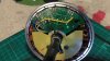
I then tested each hall sensor. I don't know if maybe I was turning the wheel too far when I tested previously but it was really clear that two were fine and one was not - the yellow wire. I tested continuity on the pcb from the soldered connection to the sensor and the yellow had no continuity while the others did. The middle sensor is fitted in the opposite orientation to the outside two. This seemed to be a clear break in the track on the pcb, so I soldered a jumper between the yellow wire and the sensor as in the photo. The motor then worked!!!
I don't think this was caused by a poor connection in the 9 wire cable where it entered the hub. I suspect the issue which caused the hall sensor anomaly was a poor track on the pcb which was intermittent for a while and eventually split as the bike was ridden over rough ground.
Anyway, problem solved and I can use my bike again!!IMAG0247.jpg
 
  • Like
Reactions: danielrlee and sjpt

Nealh

Esteemed Pedelecer
Aug 7, 2014
20,126
8,226
60
West Sx RH
Good work using a jumper to make a fix, make sure the jumper though is secure. Glue it down if poss and then use a bit of silicone for a permanent job.
 

Swell6

Finding my (electric) wheels
Sep 30, 2020
15
2
Good work using a jumper to make a fix, make sure the jumper though is secure. Glue it down if poss and then use a bit of silicone for a permanent job.
I resoldered it as it was only there for a test, and used a dab of JB Weld in the middle so it was a good secure fix. All now refitted on the bike and all working fine.
The only trade-off is the fact that I had to shorten the 9 wire cable, so the routing to the controller was a bit more tricky, but OK. I might swap that for a new one at some point.
I did try an off the bike method for testing the hall sensors but it wasn't successful, not sure why. I supplied 5v to the red & black & tested for hall sensor switching by checking voltage across ground & each coloured wire. Just wasn't picking up a measurable voltage. Maybe it needs the main 3 phase cables to be connected for that to work, though I can't imagine why. Would have been handy if that had worked.
 

vfr400

Esteemed Pedelecer
Jun 12, 2011
9,822
3,986
Basildon
I resoldered it as it was only there for a test, and used a dab of JB Weld in the middle so it was a good secure fix. All now refitted on the bike and all working fine.
The only trade-off is the fact that I had to shorten the 9 wire cable, so the routing to the controller was a bit more tricky, but OK. I might swap that for a new one at some point.
I did try an off the bike method for testing the hall sensors but it wasn't successful, not sure why. I supplied 5v to the red & black & tested for hall sensor switching by checking voltage across ground & each coloured wire. Just wasn't picking up a measurable voltage. Maybe it needs the main 3 phase cables to be connected for that to work, though I can't imagine why. Would have been handy if that had worked.
Hall sensors often won't switch back up unless you have a pull-up resistor between the signal wire and the 5v. Those resistors will be on the controller's pcb, so if you disconnect from the controller, the voltage will stay at 0v. Some hall sensors have an included pull-up resistor. You have to look at the data sheet, though it's pretty clear that yours don't.
 
  • Like
Reactions: Swell6

Advertisers