Help/Advice with 24V Battery

moremeba

Pedelecer
Mar 24, 2015
27
1
58
Hi all, was wondering if someone could assist me please?
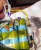
My 24V battery has gone LV on a bank of cells so subsequently the BMS has cut out.
I have measured the voltage on and all but 2 banks are reading 4.12 volts, with one bank reading 3.8v and the other reading 0.30 volts.
Is there anyway i can just re-charge the low bank to see if i can get the BMS to kick in again and then do a balance charge up?
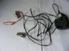
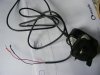
Photos below
Any help really appreciated.

Cheers
Barry
1549109358005.png
1549109414106.png
 

Nealh

Esteemed Pedelecer
Aug 7, 2014
19,990
8,172
60
West Sx RH
The side you show is of cell goups #7 (3.8v), 5 (0.3v) , 3 &1 (4.12v) , what about the voltages on the opp side 2,4 & 6 ?
Most likely the BMS has failed and the bleed resistors on group #5 have remained open and has allowed total discharge, the BMS should (if working correctly) prevented this and lvc should have come in at about 2.8 - 3.3v.
You can try to manually charge the cell group using an old 5v 0.5a phone charger and carefully monitoring voltage increase to prevent the cells going to high.
Cut the charge end off and solder on a pcb pin to each wire (a pin that fits in to the sense wire jst connector), identify the correct cell group pin on the jst connector and place the red lead/pin in to it and the black pin to the cell group pin out before and see if it charges up.
Alternately you could attach solder small/tiny croc clips to each wire end and then attach to a bare portion of the corresponding pair of the sense wires (just remember to insulate after finishing.
Bring all low groups up to 4.12v and leave to rest for 48 - 72 hrs without the bms connector connected to see if the cells maintain keep voltage, if knackered they will manually drain down.
If they don't then consider replacing the bms but most likely the cell groups are damaged even if they hold voltage and may crash under load, only time will tell.


Phone charger with crocs and pcb pins.
DSCF0948.JPGDSCF0949.JPG
 
Last edited:

Nealh

Esteemed Pedelecer
Aug 7, 2014
19,990
8,172
60
West Sx RH
The first cell group with black discharge lead (side A even # cells ) is 0v the opp end (side B odd # cells) is #1 so up to 4.2v then coming back to this side A next group is # 2 alternate each side and cell group along to get the cell group count. The final cell group #7 has the Red discharge lead.

So side A Black lead attached goes #0, #2, #4 & #6.
Opp side (B) goes #1, #3 #5 & #7 (red lead).
 

moremeba

Pedelecer
Mar 24, 2015
27
1
58
Thanks for the quick reply Nealh.
Could you just explain this sentence a little further please?
"identify the correct cell group pin on the jst connector and place the red lead/pin in to it and the black pin to the cell group pin out before and see if it charges up."
Do you mean connect the red+ side of the phone charger to the connector on the LHS of this photo or to the one on the BMS board?
Where would i need to connect the Black- side of the phone charger please?

Regards
Barry

1549114782209.png
 

Attachments

Nealh

Esteemed Pedelecer
Aug 7, 2014
19,990
8,172
60
West Sx RH
I replied shortly before heading off to work so didn't have time to look at the pic too carefully. Most BMS jst connectors for the sense wiring have an extra pin and is B0/- and connects to the first cell negative, in your case you don't have the eighth wire and just the seven B1+ - B7+ wires.

For your low cell I would connect like so as in the remarked pic of yours, the charger is only 5v so will blow if you connect it any other way.
(If you connect + wire to cell#5 and - wire to thick black/0v then the charger would see 16v+ and would blow).

.

1549114782209_LI.jpg

If the 1st cell was low then the - wire would connect to the thick black wire at 0v.
 

Attachments

Last edited:

moremeba

Pedelecer
Mar 24, 2015
27
1
58
Many thanks for the explanation Nealh. i will give this a try today to see if i can bring the cells up and let you know the outcome.
Regards
Barry
 

Nealh

Esteemed Pedelecer
Aug 7, 2014
19,990
8,172
60
West Sx RH
As usual just be careful and don't allow the charger contacts to short against each other when powered up and also when connected to battery jst connector.

If the low cell group/s do take a charge, charging may take 2 or 3 days with a 0.5a charger, slow is the way to go. Make sure you are able to monitor the charging, don't go out or leave charging to get on with it in case of any issues. Disconnect overnight when sleeping and to be safe place the cells in a safe place like an oven or open fire (unlit of course). Monitor often with a meter to check progress, don't allow over charge.
 
Last edited:

moremeba

Pedelecer
Mar 24, 2015
27
1
58
Hi Nealh, thought i would let you know the cells did not hold a charge so i guess they will will need replacing. I have contacted Jimmy at Innsat to see if he can re-furbish the pack for me.
Thanks again for taking the time to reply to my posts and the pointers you gave me, your advice will certainly help me troubleshoot any similar problems i may come up against in the future.
Best regards
Barry
 

Advertisers