how do I remove the speed limit on an Ananda controller

freddofrog

Pedelecer
Jan 6, 2012
69
14
East Midlands
Well I joined this forum just over 3 years ago, having bought a folding Izip with 20" wheels and wished I hadn't.
I then decided to wait for the warranty to run out before doing anything else.
Warranty ran out 2 years ago, and now I really have decided to do something.
I have a good idea what my requirements are, and I'm going to get a kit for a non-electric mountain bike that I also own ....I have several questions about that, but before I ask them, I thought I'd tinker with the Izip (the battery & controller & motor & frame are all in good condition, but its value is now very low)

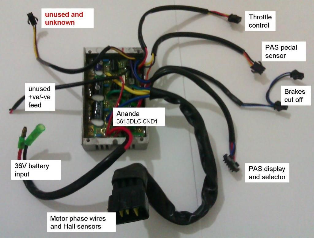
First thing I want to do is remove the speed limit on the controller. The controller is an Ananda 3615DLC-0ND1
The reason I want to remove the speed limit is because I can't make up my mind whether to go for a 250W kit or 500W kit, and since the Izip is 250W I thought I'd see what >15mph is like (assuming that it will go a tad faster.....on private land of course).

Here is the controller with the lid removed and I've labelled the wires. It's the unused/unknown connector that puzzles me (top left). I have read in another thread here, and elsewhere, that the Ananda controllers have a lead like that associated with the speed limit ..... but could it be for something else in this Ananda version ?


There are also 4 "jumpers" in the controller as shown in the close-up below, and you can see that the unused/unknown terminates in that area too.


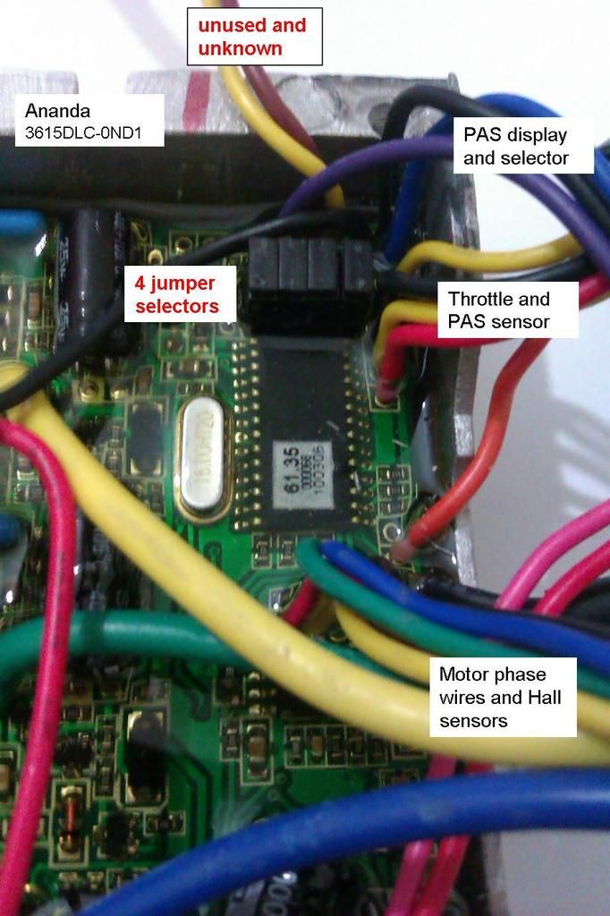
Does anyone have any ideas ?

:confused::eek:
 

trex

Esteemed Pedelecer
May 15, 2011
7,703
2,671
it is probably not restricted if it does not have these two white wires joined together:

 
D

Deleted member 4366

Guest
The modern Ananda controllers have the speed limit set by software, but you can access it through the LCD if you have one. My guess is that it's one of those jumpers. Try each in turn to see what happens.

The spare wires might be for lights at battery voltage. You should be able to check them with a voltmeter. If you have a light switch on your display, they'll only be live when switched on.
 

freddofrog

Pedelecer
Jan 6, 2012
69
14
East Midlands
it is probably not restricted if it does not have these two white wires joined together:

yeah I'd already found that image on another forum by googling my controller, but I'm assuming that that 3615DLC-2FJ0 is different from my 3615DLC-0ND1.

My Izip also just feels restricted, because it always seems to reach the same top speed whatever the tyre pressures are, or whether I'm on grass or tarmac.

I also bought the bike new just over 3 years ago from a shop, and I would have thought it came restricted. I looked inside the case where the controller is when I'd had the bike a few months, and that unused/unknown connector was like that then (I have a photo taken at the time).
 

freddofrog

Pedelecer
Jan 6, 2012
69
14
East Midlands
The modern Ananda controllers have the speed limit set by software, but you can access it through the LCD if you have one. My guess is that it's one of those jumpers. Try each in turn to see what happens.

The spare wires might be for lights at battery voltage. You should be able to check them with a voltmeter. If you have a light switch on your display, they'll only be live when switched on.
The PAS display and selector is just one of those LED things, no LCD. No lights either.

I think that the "unused +ve/-ve feed" in my first photo is for lights.

I'm wondering if that "unused/unknown" connector is for accessing/programming the chip, because it does terminate down in that area.

Any guess as to why there are 4 jumpers ?
 
D

Deleted member 4366

Guest
Here's my guesses: One jumper will be for speed limit, one to reverse the motor, one for 60 deg motor phase angle and one to run at a different voltage. No harm will come by trying without the jumpers. They only set inputs on the cpu high or low. Try each one in turn.

You can tell if your motor is limited by checking the speed with the wheel off the ground. If it always goes the same speed regardless of the charge in the battery, it's limited. If it goes 30% faster when fully charged than with a flat battery, it isn't limited.
 
  • Like
Reactions: freddofrog

freddofrog

Pedelecer
Jan 6, 2012
69
14
East Midlands
Thanks, I have done that sort of "wheel off the ground" thing before (not as test) when demonstrating it to people before they have a go. The bike has a stand, so I lean it over on the stand, and demo the throttle. AFAIK the wheel does as you describe, but I wouldn't swear to it. I need to go out and run the battery down LOL

Those guesses are interesting, I'll give it a go.

When I'm a bit more happy with what those jumpers do, if I put a 12V SLA in series to bump the volts up to 48V, would that be ok as a quick further test ?

Obviously I take responsibility if the FETs blow, but the reason I ask is because I'm assuming that a quick test at 48V would get the bike over 15 mph when the controller is de-restricted ?
 

freddofrog

Pedelecer
Jan 6, 2012
69
14
East Midlands
I didn't think of that :eek: I might see if I can read the FETs too

will 48V give it a boost, would a 12V SLA be ok in series for a few minutes ?

(as I say, only a quick try, just to get a feel for it, this is just the first step towards a kit)
 
D

Deleted member 4366

Guest
Only connect the 48v if the capacitor/s are at least 56v otherwise you get a lot of stinky smoke.
 
  • Like
Reactions: freddofrog

freddofrog

Pedelecer
Jan 6, 2012
69
14
East Midlands
ok ....I'll have to take the controller out again. I really am starting to hate this Izip now. At least its taught me to make my own e-bike next time.

The only redeeming feature of this thing is that it folds up and goes in the boot of a car nicely, but in 3 years that was useful once.
 

freddofrog

Pedelecer
Jan 6, 2012
69
14
East Midlands
I've had a look in the controller again, and I can't see the voltages on the capacitors, because they are lying flat with the voltage rating on the other side, and there is a thick clear gel over them to hold everything down, so I decided to leave them alone.

I also tried the jumpers one at a time .....
the left one made no difference
next one in and the PAS LEDs were flashing and nothing would work
next one in the same except it did work
last one (on the right) was same as first one on the left.

So I might short that spare "unknown/unconnected" lead ?

Also, while the controller was hanging out, I decided to get out my hydraulic cycle trainer and put the Izip in it (I did this 3 years ago). There are several settings on the hydraulic dyno ... maximum represents a 3.3% gradient, and minimum represents 0% gradient. The cycle trainer's display also shows road speed (which is based in the rotational speed of the dyno). I also measured battery voltage and current into the controller.

Results ....
0% gradient, speed = 24 km/hr, volts = 39, amps = 4
3.3% gradient, speed = 22 km/hr. volts = 38. amps = 7

With dyno retracted I can't get the speed of the rear wheel, but volts = 40, amps = 0.5 and wheel speed looks and sounds the same. Motor is a Currie motor btw.

Correct me if I'm wrong, but that seems speed restricted, and the Currie motor is probably 250 W ???

Are these Currie motors any good, or are they relatively old and inefficient ?
 

trex

Esteemed Pedelecer
May 15, 2011
7,703
2,671
result is too close to call.
If the bike can get over 10A then you could say it's restricted for certain.
 
  • Like
Reactions: freddofrog
D

Deleted member 4366

Guest
Don't short those wires. If they have battery boltage on them, you'll see sparks.
 

freddofrog

Pedelecer
Jan 6, 2012
69
14
East Midlands
Don't short those wires. If they have battery boltage on them, you'll see sparks.
I'll check beforehand, maybe use a resistor, but I doubt if they have battery voltage, as wires with battery voltage will be "unused +ve/-ve feed" in the first picture


edit: but do you think that since the jumpers don't appear to be associated with speed restriction, if there is a simple way to de-select restriction, then it will be that "unknown/unused" pair ?
 

freddofrog

Pedelecer
Jan 6, 2012
69
14
East Midlands
Earlier results ....
0% gradient, speed = 24 km/hr, volts = 39, amps = 4
3.3% gradient, speed = 22 km/hr. volts = 38. amps = 7

More results ....
slowing-by-shoe 1, speed = 20 km/hr, volts = 37, amps = 10
slowing-by-shoe 2, speed = 17 km/hr, volts = 36, amps off the scale

note:
volts measured on a Fluke DMM
amps measured on an old analog Avo on 10 Amp range (max DC range) with about 11 Amps f.s.d.

I might swap them round, the Fluke also has a 10 Amp range (un-fused), it might show some numbers > 10
 
D

Deleted member 4366

Guest
You can make an ammeter out of a piece of 14g battery wire and a voltmeter. Cut a piece about 10cm long and connect it inline with one of the battery wires. Clip your voltmeter probes to each end. The voltage drop is proportional to current. You can use your fluke at 10A to calibrate it.

You get maximum current when you slow the wheel right down. You can use the brake for that if you disconnect the brake switch. Don't fo it gor too long and don't stop the motor completely.
 
  • Like
Reactions: freddofrog

freddofrog

Pedelecer
Jan 6, 2012
69
14
East Midlands
You can make an ammeter out of a piece of 14g battery wire and a voltmeter. Cut a piece about 10cm long and connect it inline with one of the battery wires. Clip your voltmeter probes to each end. The voltage drop is proportional to current. You can use your fluke at 10A to calibrate it.

You get maximum current when you slow the wheel right down. You can use the brake for that if you disconnect the brake switch. Don't fo it gor too long and don't stop the motor completely.
thanks for that DIY but I had a simpler idea which turned out even simpler.

I knew that I had another analogue meter in the loft somewhere which I thought would go up to 10A as well, and I thought that if it did I would put it in series with the Avo to check that they both read the same, then put them in parallel.

When I found it in the loft, it was a Philips in its case, hardly ever used, and it goes up to 30A DC !!!!!

All results ....
0% gradient, speed = 24 km/hr, volts = 39, amps = 4
3.3% gradient, speed = 22 km/hr. volts = 38. amps = 7

slowing-by-brake 1, speed = 20 km/hr, volts = 37, amps = 10
slowing-by-brake 2, speed = 17 km/hr, volts = 36, amps = 12
slowing-by-brake 3, speed = 10 km/hr, volts = 36, amps = 12

(slowing-by-brake = gripping dyno flywheel with a TV Times magazine LOL)

I even took it down to 5 km/hr very briefly, and the volts and amps held up.

So ...
1. is it restricted ?
2. is it 250 W ?
3. is there a chance that that "unknown/unused" connection is somehow associated with de-restriction ?
 

freddofrog

Pedelecer
Jan 6, 2012
69
14
East Midlands
I decided to short out the "unknown/unused" connection.

Before I did, I measured the voltages. Brown = 0V, Yellow = 5V

So I put a 10k resistor into the 5V hole and a resistor-end-cut into the 0V hole of the connector. Then measured the voltage and current with the 10k resistor going back to the 0V through the current meter.

Voltage on yellow dropped to 3.78 V, current was 350 uA. That tells me that there's a 3.74k "pull up" in the yellow connection, which would give about 1.5 mA if brown and yellow are shorted ....which it did.

And it makes no difference. I even removed the battery and made sure all volts had gone from the controller, then powered it back up with the connector shorted. Still max speed of 24 km/hr in the bike trainer on 0% gradient.

I wonder if it's worth contacting Ananda http://www.ananda.com.cn/
 

Advertisers