Hi,
Trying to understand the wiring and signals between throttle and controller. I have it working again but think I just got lucky.
First, some background. My son's e-scooter was running rough recently after taking it through flood waters. Probably 100+ mm deep. Water entry seemed obvious but when he opened the battery / controller compartment it was bone dry and well sealed.
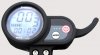
The throttle was less well sealed so he bought one that looked the same. Meant for a Speedway 3 scooter. Then his scooter supplier (Lunar Cycle in the US, selling a re-badged scooter from NTE in China) sent him a freebie throttle. The throttles all look the same other than the Speedway one having a Speedway label on the front and a bonus USB phone charging port on the rear. Sheer luxury.
None of these solved his problem so he called me in as his standby electrical engineer. I probed around with a CRO and meter. Things were definitely rough and intermittent. Mostly, his front motor would run but the rear motor was reluctant to kick in. Gradually, things degraded until neither would start. I brought it back to my workshop.
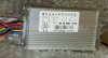
This is where it got interesting. It was clearly a controller issue and there seemed to be a dead CPU in one of the two controllers. Both controllers are built on a common PCB that seems fairly well documented for the KU63. These are higher spec'd variants running 52V and are 25A rated. The throttle has a 6-wire interface. and I sussed out 4 of those. There are 2 more I could not identify but they both carry bursts of 0/5V digital data. I was able to establish that one (a yellow wire) came from the TxD pad on the PCB of the rear controller and transmitted data to the throttle unit. The other (a blue wire) goes to the RxD pad on the PCBs of both controllers. Similar but different data bursts and this time heading south from the throttle. The waveform on this line was distorted with a weird mid-voltage 3rd state occasionally. I was able to isolate this to a loading by the rear wheel CPU.
At this point I bought a couple of new controllers from Passion Gadgets in Singapore. Their "SPEEDWAY3 52V 25A CONTROLLER". It looked identical to the original and the Speedway 3 moniker augured well. And so it was. I got lucky. Dropped them in and we're all good with 2 spare throttles to boot.
This leads me to the main reason for my post. I am curious. Hey, I'm a design engineer. I cannot find any info on what those two signals are. I assume the yellow wire includes speed data. But a couple of hundred bits in each data burst? And the blue wire has a similar volume of data. What is that for? I'd love to hear people's thoughts.
FWIW, none of the FET switches had failed short which is the usual failure mode. I ordered some replacements and will look at the dead controllers in due course. I don't hold much hope for the rear controller where I assume the CPU is dead. But why did it die? Only thing I can think of is the long wires from throttle to controllers go directly to unprotected CPU pins. So they are very exposed to any transients. Not even a buffer chip. Made to a price. Maybe I'll tack some Tranzorbs onto the PCBs.
Sorry for the lengthy post. Happy to hear people's thoughts or to help anyone else with the stuff I have learnt in this project.
Happy scooting,
John
Trying to understand the wiring and signals between throttle and controller. I have it working again but think I just got lucky.
First, some background. My son's e-scooter was running rough recently after taking it through flood waters. Probably 100+ mm deep. Water entry seemed obvious but when he opened the battery / controller compartment it was bone dry and well sealed.
The throttle was less well sealed so he bought one that looked the same. Meant for a Speedway 3 scooter. Then his scooter supplier (Lunar Cycle in the US, selling a re-badged scooter from NTE in China) sent him a freebie throttle. The throttles all look the same other than the Speedway one having a Speedway label on the front and a bonus USB phone charging port on the rear. Sheer luxury.
None of these solved his problem so he called me in as his standby electrical engineer. I probed around with a CRO and meter. Things were definitely rough and intermittent. Mostly, his front motor would run but the rear motor was reluctant to kick in. Gradually, things degraded until neither would start. I brought it back to my workshop.
This is where it got interesting. It was clearly a controller issue and there seemed to be a dead CPU in one of the two controllers. Both controllers are built on a common PCB that seems fairly well documented for the KU63. These are higher spec'd variants running 52V and are 25A rated. The throttle has a 6-wire interface. and I sussed out 4 of those. There are 2 more I could not identify but they both carry bursts of 0/5V digital data. I was able to establish that one (a yellow wire) came from the TxD pad on the PCB of the rear controller and transmitted data to the throttle unit. The other (a blue wire) goes to the RxD pad on the PCBs of both controllers. Similar but different data bursts and this time heading south from the throttle. The waveform on this line was distorted with a weird mid-voltage 3rd state occasionally. I was able to isolate this to a loading by the rear wheel CPU.
At this point I bought a couple of new controllers from Passion Gadgets in Singapore. Their "SPEEDWAY3 52V 25A CONTROLLER". It looked identical to the original and the Speedway 3 moniker augured well. And so it was. I got lucky. Dropped them in and we're all good with 2 spare throttles to boot.
This leads me to the main reason for my post. I am curious. Hey, I'm a design engineer. I cannot find any info on what those two signals are. I assume the yellow wire includes speed data. But a couple of hundred bits in each data burst? And the blue wire has a similar volume of data. What is that for? I'd love to hear people's thoughts.
FWIW, none of the FET switches had failed short which is the usual failure mode. I ordered some replacements and will look at the dead controllers in due course. I don't hold much hope for the rear controller where I assume the CPU is dead. But why did it die? Only thing I can think of is the long wires from throttle to controllers go directly to unprotected CPU pins. So they are very exposed to any transients. Not even a buffer chip. Made to a price. Maybe I'll tack some Tranzorbs onto the PCBs.
Sorry for the lengthy post. Happy to hear people's thoughts or to help anyone else with the stuff I have learnt in this project.
Happy scooting,
John